
Hybrid composite flywheel rim and its manufacturing method

a hybrid composite and flywheel technology, applied in mechanical energy handling, mechanical equipment, other domestic objects, etc., can solve the problems of low performance of such flywheel rotors, strain matching between, and speed typically limited to around 400 m/s

Inactive Publication Date: 2006-07-25
BEACON POWER LLC
View PDF7 Cites 11 Cited by
  • Summary
  • Abstract
  • Description
  • Claims
  • Application Information

AI Technical Summary

Benefits of technology

[0010]It has been found more macroscopically uniform fiber distribution may be important to achieve uniform stress distribution during rotor spinning even with the constant mixture ratio between glass and carbon fibers.

Problems solved by technology

Earlier flywheel UPS systems used flywheel rotors constructed of steel due to simplicity, however the performance of such flywheel rotors are low with tip speeds typically limited to around 400 m / sec or less.
One of the key issues to have workable composite flywheel rim is strain matching between the ID of the rim and OD of the hub.
More glass fibers results in lower cost, but a greater mismatch of the diameter growths could be generated during rotor spinning.
The drawback of a rim made of all-glass fiber layers and all-carbon fiber layers is stress and strain discontinuities at the interface between glass and carbon composites which may result in possible cracks during fabrication and operation.
This can be a desirable solution, however it is not easy to make a rim like this and must result in high cost.
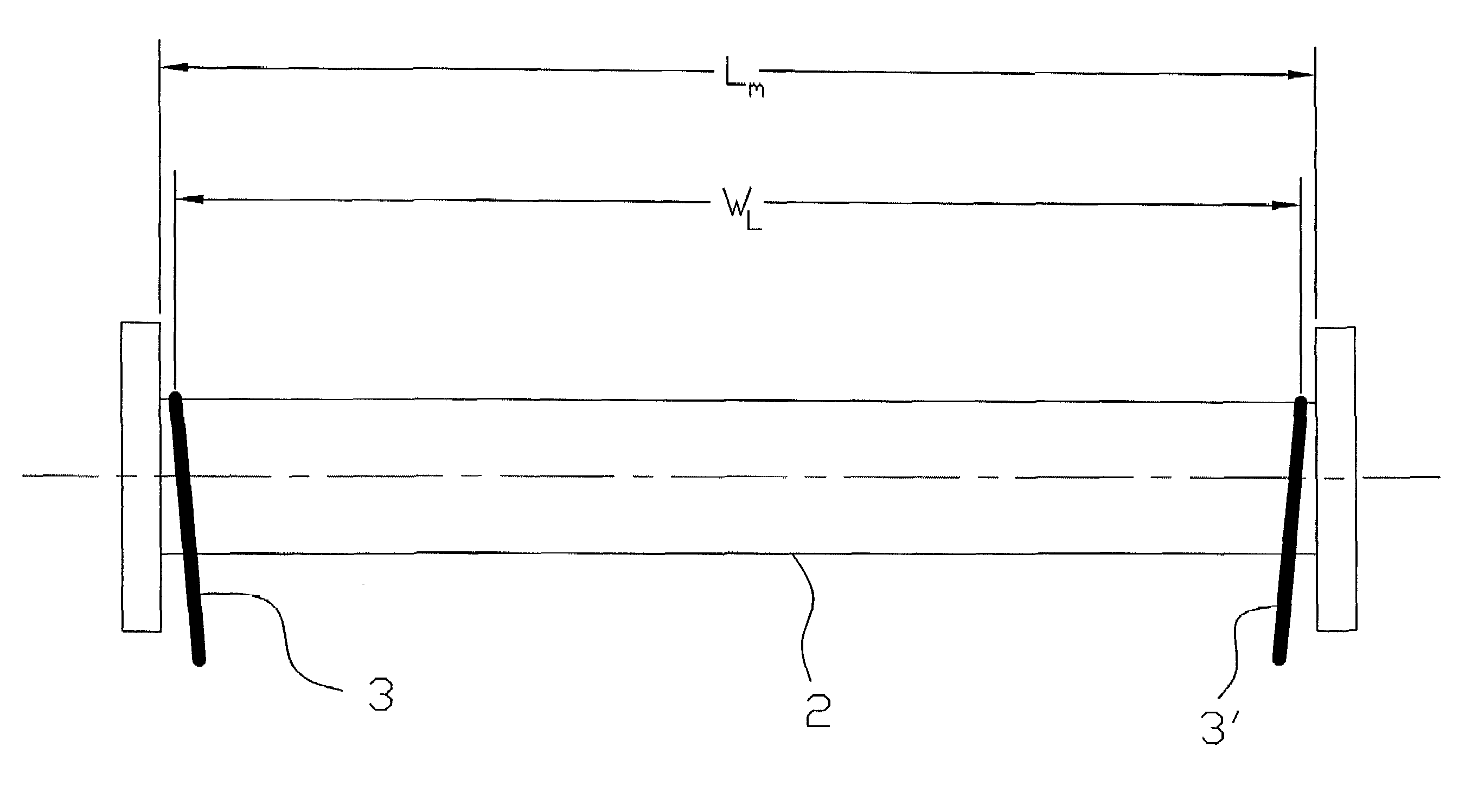
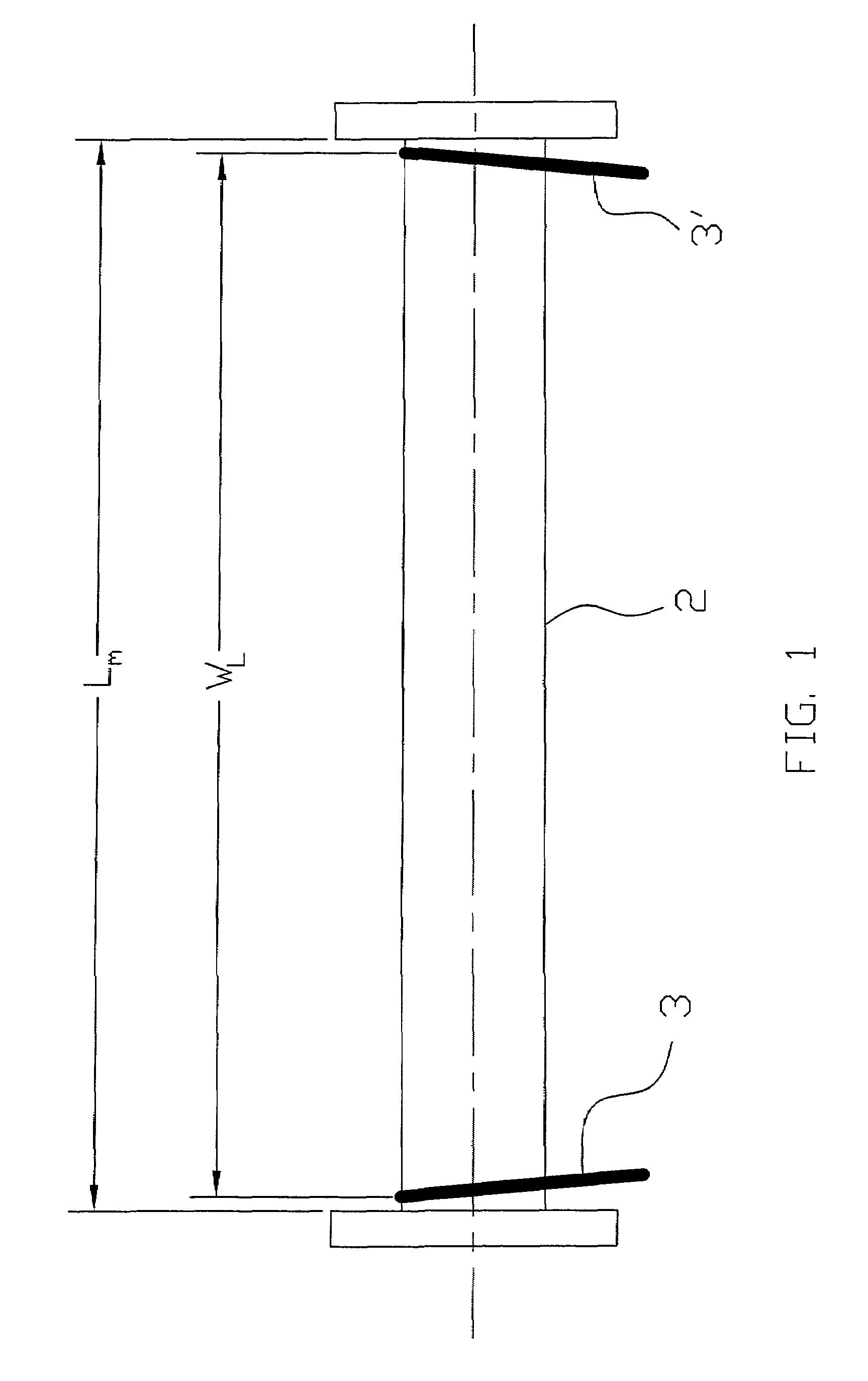
However, it has been discovered that occasionally, by chance, the carbon fiber tows in the band are laid down in a radially aligned pattern, as shown in FIG. 1, which produces an undesirable distribution of glass and carbon fibers and could result in large internal shear forces between the aligned or stacked carbon fiber regions and the adjacent aligned or stacked glass fiber regions.

Method used


Image

  • Hybrid composite flywheel rim and its manufacturing method
  • Hybrid composite flywheel rim and its manufacturing method
  • Hybrid composite flywheel rim and its manufacturing method

Examples


Embodiment Construction

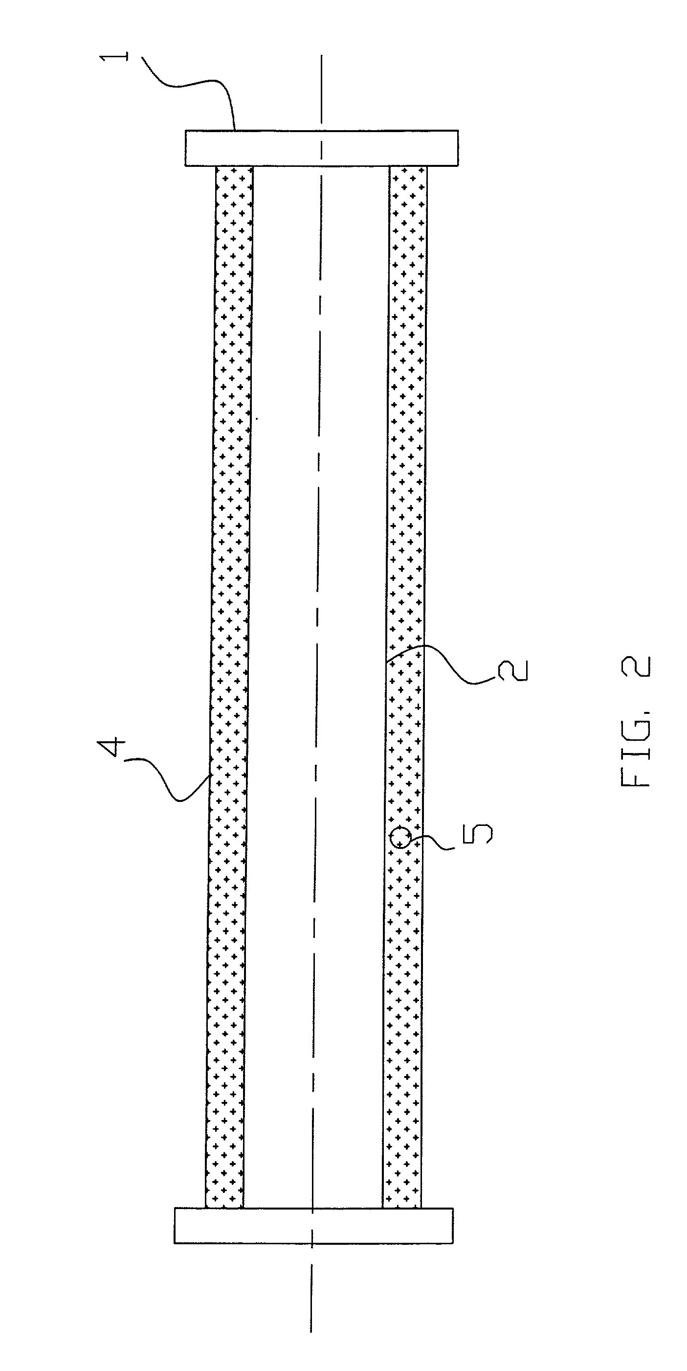
[0018]Turning to the drawings, wherein like characters designate identical or corresponding parts, and more particularly to FIG. 1 thereof, a mandrel 2 is shown for winding resin-impregnated tows in a fiber band 3 to produce an elongated annular composite “log”4, shown in FIG. 2, which can be cut into numerous shorter annular flywheel rims. The process and apparatus for winding the fiber tows onto the mandrel is illustrated in fUll detail in U.S. patent application Ser. No. 09 / 951,844 entitled “High-Speed Manufacturing Method for Composite Flywheels” filed on Sep. 11, 2001 by Christopher W. Gabrys and assigned to the assignee of this application. The disclosure of this application Ser. No. 09 / 951,844 is incorporated herein by reference.

[0019]The mandrel 2 has two end flanges 1 which help confine the resin-impregnated fiber tows on the ends of the mandrel 2 as the fiber band 3 is being wound. The length (Lm) of the mandrel 2 is the full length between the facing surfaces of the two f...


PUM

PropertyMeasurementUnit
speedsaaaaaaaaaa
speedsaaaaaaaaaa
elastic moduliaaaaaaaaaa

Abstract

A composite flywheel rim has multiple fiber layers in each of a plurality of radially contiguous zones. The layers in the intermediate zones each have a mixture of carbon fiber tows and glass fiber tows. The ratio of carbon fiber tows to glass fiber tows in each layer of any single zone is constant and the ratio incrementally increases zone-by-zone radially toward the outside of the rim, and the distribution of carbon fiber tows is macroscopically uniform in each zone. The flywheel rim is made by winding a band of fiber tows, impregnated with wet resin, onto a mandrel. The macroscopically uniform distribution can be achieved by controlling the correlation between lead rate of the fiber band as it is wound onto the mandrel per mandrel revolution and the winding length. Carbon fiber tow spacing and position in the band, and a width of a carbon fiber tow also affect the lay up pattern, however, the most effective and the easiest way to change the lay up pattern with constant parameters is by controlling the winding length.

Description

[0001]This is related to U.S. Provisional Application 60 / 242,222 filed on Oct. 20, 2000 and entitled “Hybrid Composite Flywheel Rim and its Manufacturing Method”.BACKGROUND OF THE INVENTION[0002]Flywheel systems have been used for many years for storing energy in a system, and then releasing that stored energy back into the other system. Flywheel systems provide a smoothing effect to the operation of internal combustion engines and other kinds of power equipment. More recently, flywheel systems are being used in electrical applications for uninterruptible power supplies, UPS, by storing and releasing energy. Electrical energy storage flywheel systems, which include a flywheel rotor and an attached motor / generator, convert electrical energy to mechanical energy by using the motor to accelerate the flywheel rotor. The energy is stored kinetically in the motion of the flywheel rotor. Mechanical energy is then later converted back to electrical energy when required by using the generato...

Claims


Application Information

Patent Timeline
Patent Type & Authority Patents(United States)
IPC IPC(8): H02K7/02B29C53/66B29C53/80B29C70/08B29C70/32F16F15/305
CPCB29C53/8041B29C70/08F16F15/305B29C70/32B29C53/66Y10T74/212B29L2031/322Y10T74/2132
Inventor DETORE, WILLIAM L.KYONO, TETSUYUKI
Owner BEACON POWER LLC
Learn More