Thermoelectric module

a technology of thermoelectric modules and thermoelectric modules, applied in the direction of lasers, basic electric elements, semiconductor lasers, etc., can solve the problems of deteriorating performance of thermoelectric modules and great heating values at electrodes, and achieve the effect of reducing electric power consumption of them

Inactive Publication Date: 2006-07-25
YAMAHA CORP
View PDF5 Cites 10 Cited by
  • Summary
  • Abstract
  • Description
  • Claims
  • Application Information

AI Technical Summary

Benefits of technology

[0010]In addition, a temperature-controlled semiconductor module can be realized by combining a thermoelectric module with a semiconductor component such as a semiconductor laser. Herein, the the

Problems solved by technology

This causes great heating values at electrodes, which m

Method used


Image

  • Thermoelectric module
  • Thermoelectric module
  • Thermoelectric module

Examples


Embodiment Construction

[0024]This invention will be described in further detail by way of examples with reference to the accompanying drawings.

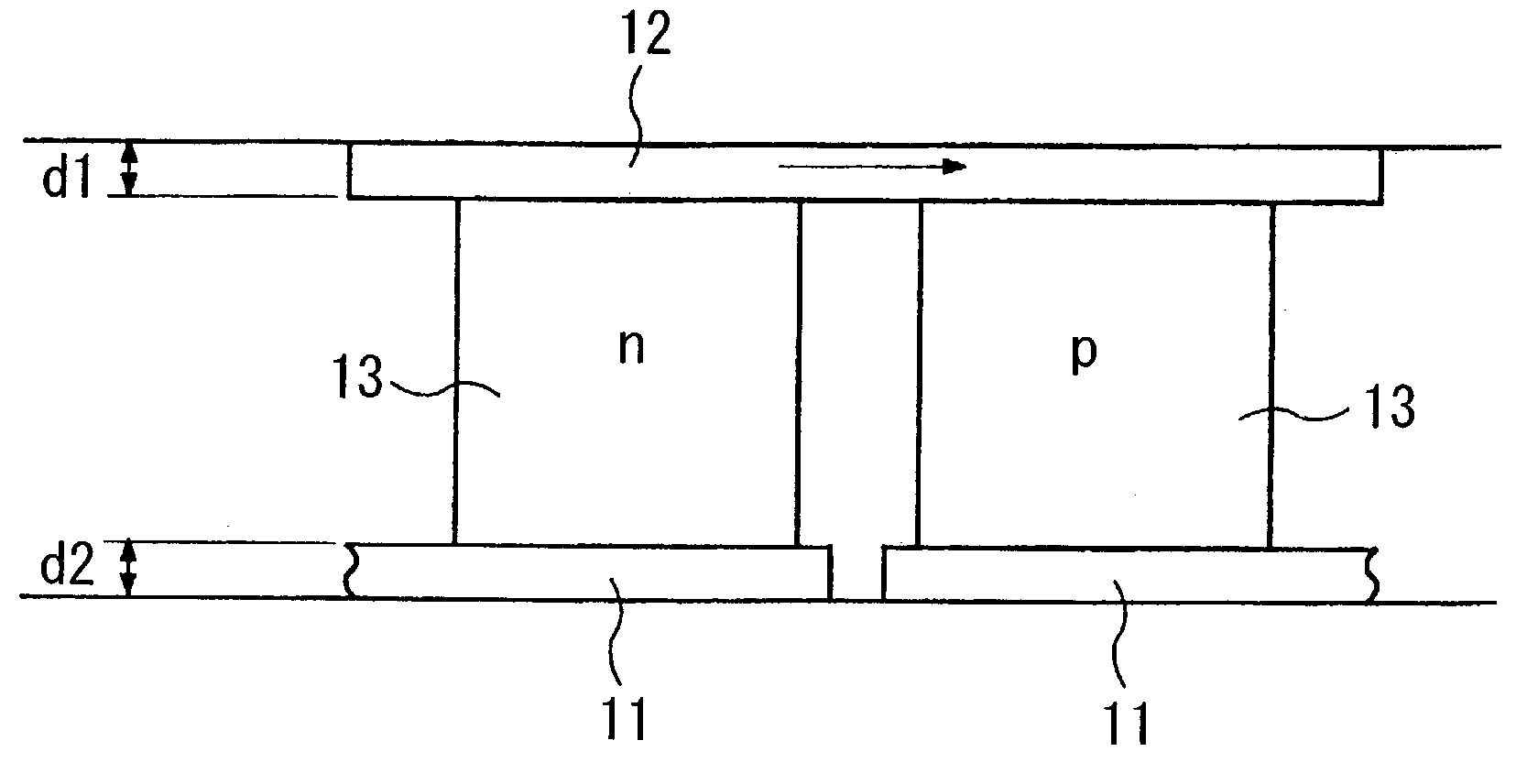
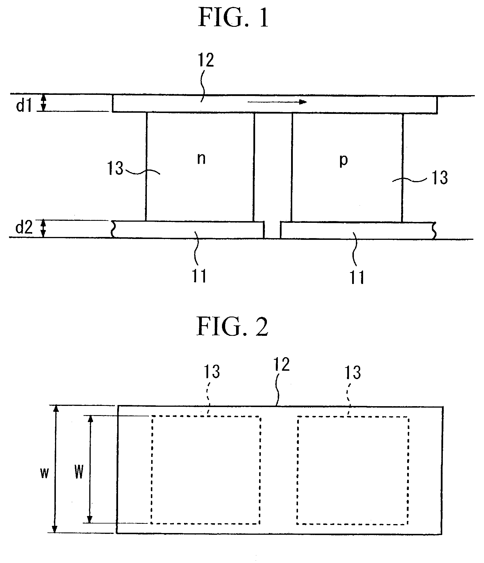
[0025]FIG. 1 is a front view showing the essential structure of a thermoelectric module containing electrodes and thermoelectric elements in accordance with a preferred embodiment of the invention; and FIG. 2 is a plan view of the thermoelectric module. Herein, a pair of thermoelectric elements 13 consisting of an n-type and a p-type are arranged to adjoin together on a pair of lower electrodes 11 respectively, wherein they are both connected with an upper electrode 12. As similar to the conventional example of the thermoelectric module shown in FIGS. 4 to 7, all the lower electrodes 11, upper electrode 12, and thermoelectric elements 13 are connected together, wherein the upper electrode 12 acts as a heat absorbing side (or a cooling side). Compared with the lower electrodes 11 that act as a heat radiating side, the upper electrode 12 acting as the heat absorbing ...


PUM


Abstract

A thermoelectric module is constituted by a pair of substrates having electrodes, which are arranged opposite to each other with a prescribed space therebetween, in which a prescribed number of thermoelectric elements are arranged in such a way that a p-type and an n-type are alternately arranged, so that the thermoelectric elements are connected in series or in parallel together with the electrodes. Herein, one substrate is a heat absorption side, and other substrate is a heat radiation side. In addition, a current density in a current transmission area of the heat-absorption-side electrode is set to 50 A/mm2 or less, and a height of the thermoelectric element is set to 0.7 mm or less. Furthermore, a temperature-controlled semiconductor module can be realized by combining a thermoelectric module with a semiconductor component such as a semiconductor laser.

Description

BACKGROUND OF THE INVENTION[0001]1. Field of the Invention[0002]This invention relates to thermoelectric modules having endothermic properties for absorbing heat from electronic components and the like.[0003]2. Description of the Related Art[0004]A conventional example of a thermoelectric module comprising an upper substrate 2 and a lower substrate 1 will be described with reference to FIGS. 6 to 9, wherein FIG. 6 is a plan view showing the upper substrate 2, FIG. 7 is a right side view, FIG. 8 is a front view, and FIG. 9 is a plan view showing the lower substrate 1. The upper substrate 2 and the lower substrate 1, both of which are made of alumina, are arranged opposite to each other with a prescribed space therebetween, in which upper electrodes 5 are arranged on the upper substrate 2, and lower electrodes 6 are arranged on the lower substrate 1. The upper electrodes 5 and the lower electrodes 6 are alternately arranged to sandwich different types of thermoelectric elements 3 ther...

Claims


Application Information

Patent Timeline
IPC IPC(8): H01L35/28H01L35/32H01L23/38H01L29/66H01S5/024
CPCH01L23/38H01L29/66992H01S5/02415Y10S257/93H01L2924/0002H01L2924/00
Inventor YAMASHITA, MASAYOSHIKAMIMURA, NAOKITANOUE, FUMIYASUONOUE, KATSUHIKOHOSHI, TOSHIHARU
Owner YAMAHA CORP
Why Eureka
Try Eureka