Control system for a wind power plant with hydrodynamic gear

a technology of hydrodynamic gear and control system, which is applied in the direction of fluid pressure control, gearing, instruments, etc., can solve the problems of low operation reliability, reduced efficiency under partial load, and high effort on the part of mains supply,

Active Publication Date: 2006-07-25
VOITH PATENT GMBH
View PDF13 Cites 71 Cited by
  • Summary
  • Abstract
  • Description
  • Claims
  • Application Information

AI Technical Summary

Benefits of technology

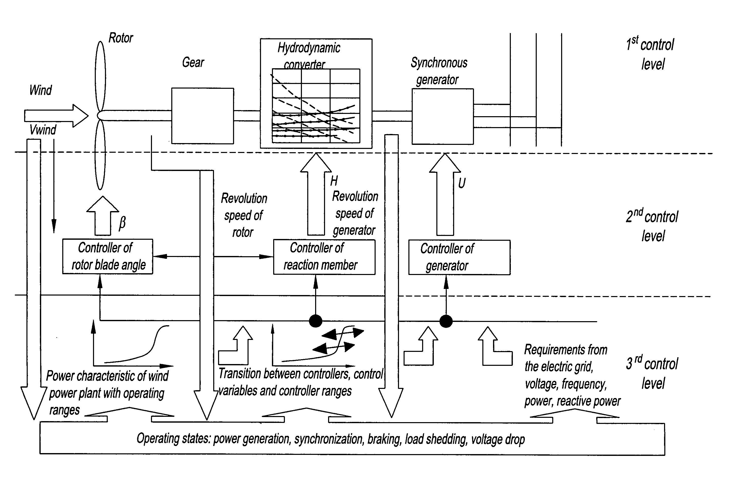
[0020]Depending on the position of a reaction member of the hydrodynamic Föttinger speed transformer, which is typically a guide wheel with guide blades, there is a specific power absorption of the pump and thus connected power transmission to the turbine wheel of the hydrodynamic Föttinger speed transformer. This leads to the consequence that as a result of the system-inherent characteristics of the power conversion from air flow to the kinetic energy of a wind rotor and the system characteristics of the speed transformer, the transmission ratios in the power split gear and the reaction member of the hydrodynamic transformer can be set in such a way that by means of system-inherent control effect of the speed transformer in conjunction with the superposition gear in general and in particular in the partial-load range of the wind power plant it is possible to achieve an optimal input speed for the wind rotor on the input shaft of the drive train with the impressed constant generator speed on the output shaft of the drive train. This leads to the consequence that wind rotor and speed transformer as turbo machines have the same characteristics of speed / power and speed / moment and identical behaviors are required for the control as a result of their identical system behavior.

Problems solved by technology

An especially disadvantageous aspect in fixed-speed wind power plants is that they can only be operated with reduced efficiency under partial load, which occurs frequently under typical wind conditions.
This approach leads away from the problem to be solved here and is linked to special problems such as the complex open-loop and closed-loop control circuits, the adversely reflected parabolic characteristics of the wind rotor in the frequency converter, the stiffness of the defined generator characteristics by the frequency converter, the lower operational reliability in the case of serious environmental restrictions, a mains supply quality to be operated with high effort such as the occurrence of only few harmonics and a low production of reactive power.
Such a system has the same problems as wind power plants with frequency-controlled generators.
This system also has the problem of difficult control characteristics, especially a sluggish response behavior and relevant idle times and strong non-linearities.
Moreover, the hydraulic system components are disadvantageous due to the constructional complexity.

Method used

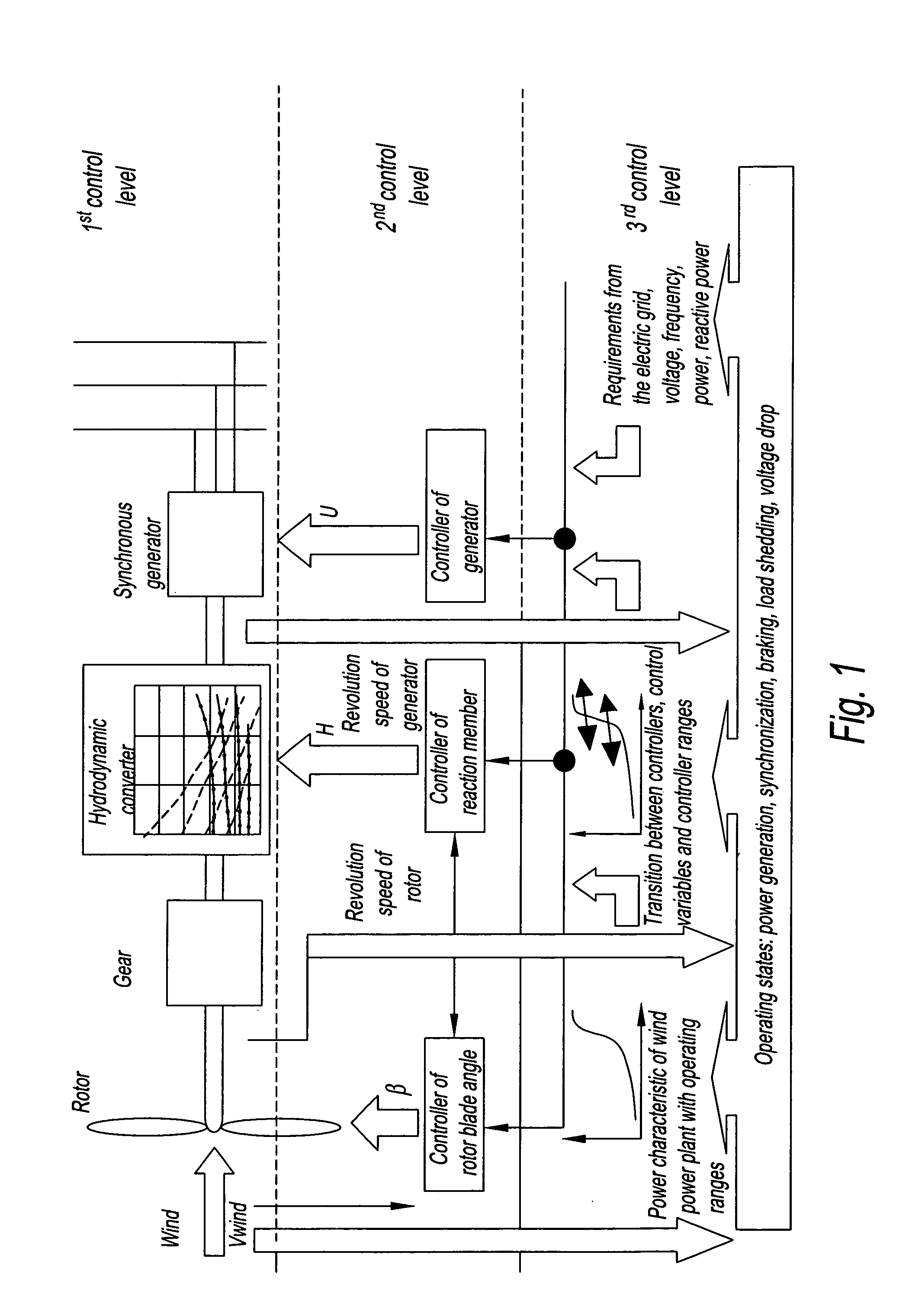
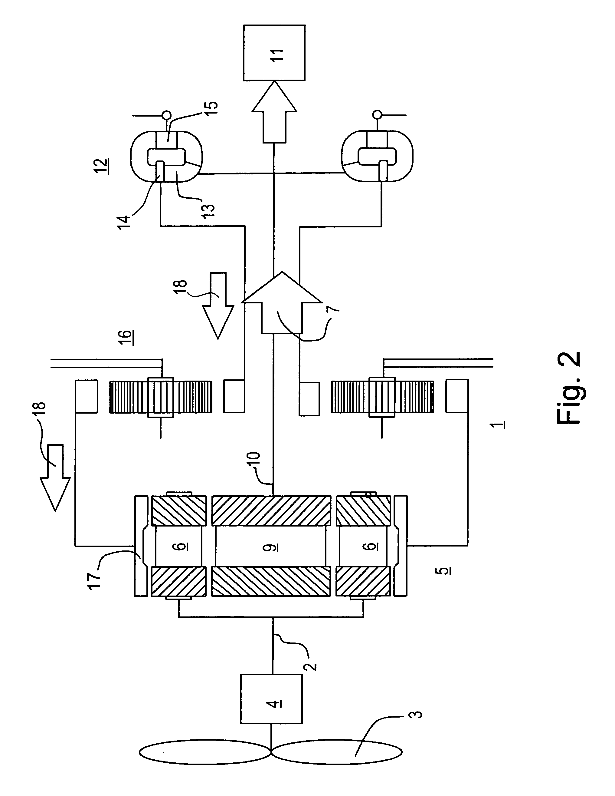

Image

  • Control system for a wind power plant with hydrodynamic gear
  • Control system for a wind power plant with hydrodynamic gear
  • Control system for a wind power plant with hydrodynamic gear

Examples


Embodiment Construction

[0041]The pR of a wind power plant is in connection in an approximated manner with the wind speed vw:

pR=k cp(vw, ωR, β)vw3  (1)

[0042]Various constants such as blade geometry and density of the air are combined here as k. cp further designates the power coefficient, which—as shown—depends on the wind speed vw, the rotor speed ωR and the angular position of the rotor blades, the so-called pitch angle. This power coefficient is characterized by a global maximum, which shifts towards higher rotor speeds ωR in increasing wind speeds vw.

[0043]FIG. 3 shows in this connection the illustration of effective power of a wind rotor by considering different wind speeds. A set of curves (unbroken lines) is shown which represents in an exemplary manner the power taken up by a wind rotor with a diameter of 70 m from the air flow at a constant rotor blade pitch angle for the wind speeds of 18 m / s, 16 m / s, 14 m / s, 12 m / s, 10 m / s, 8 m / s. The displacement of the optimal rotor speeds towards higher value...


PUM


Abstract

A wind power plant connectable to an electric grid is provided that has at least three control levels. A controller controls an angular position of the rotor blades and / or controls a setting of the reaction member of the hydrodynamic speed transformer and / or controls the power electronics of the generator. The controller is provided with predetermined setpoint characteristics depending on operating states of the wind power plant and / or the electric grid or characteristics of the wind.

Description

RELATED APPLICATIONS[0001]This application claims priority in German Application No. DE 103 61 443.5, filed on Dec. 23, 2003, the disclosures of which are incorporated herein by reference.BACKGROUND OF THE INVENTION[0002]1. Field of the Invention[0003]The invention relates to a control system for a wind power plant with a hydrodynamic gear in the drive train between wind rotor and a generator connected to the electric mains with fixed frequency.[0004]2. Description of the Related Art[0005]If attention is given to the special system characteristics of wind power plants with respect to the power input side first, there is a particularity, in addition to the progress over time of typically strongly fluctuating power potential of the air flow, in the power conversion of the mechanical power of the air flow into the mechanical power of the wind rotor. In this respect it is possible to associate each flow speed of the driving air flow with an optimal speed-to-torque ratio for the wind rot...

Claims


Application Information

Patent Timeline
Patent Type & Authority Patents(United States)
IPC IPC(8): F03D7/00F03D7/02F03D7/04F03D11/02F16H47/08F16H61/50F16H61/56G05D16/02
CPCF03D7/0284F03D7/043F03D11/02F16H47/08F16H61/56F05B2260/40311Y02E10/723Y02E10/722F05B2260/406F03D15/00F03D15/10F03D9/255Y02E10/72G05D16/02
Inventor TILSCHER, MARTINBASTECK, ANDREAS
Owner VOITH PATENT GMBH
Why Eureka
Try Eureka