Check patentability & draft patents in minutes with Patsnap Eureka AI!

Video compression and transmission apparatus and video compression and transmission method

a transmission apparatus and video compression technology, applied in the field of video compression transmission method and video compression transmission apparatus, can solve the problems of reducing mobility, burdensome preparation work such as making available satellite communication lines, and large-scale systems, and achieves the effects of improving quick reporting, maintaining mobility, and low cos

Inactive Publication Date: 2006-07-25
PANASONIC CORP
View PDF9 Cites 4 Cited by
  • Summary
  • Abstract
  • Description
  • Claims
  • Application Information

AI Technical Summary

Benefits of technology

[0011]The invention aims at providing at a low cost video compression transmission apparatus that improves quick reporting while maintaining mobility. The invention also aims at video compression transmission apparatus that can change the processing method depending on the transmission speed on communication lines and arithmetic operation performance of apparatus, thus upgrading the picture quality.

Problems solved by technology

However, this system is disadvantageous in that it requires apparatus for transmitting pictures in real time thus requiring a large-scale system.
Preparation work such as making available satellite communication lines is burdensome before starting transmission of pictures.
The live video collection system is advantageous in that it can immediately utilize pictures on news spots; it is disadvantageous in that preparation work is on a large scale such as providing a news spot with a large transmission facility and a plurality of operators thus reducing the mobility.
Another disadvantage is large costs for collection of news pictures.
On the other hand, recorded video tapes must be carried into a broadcast station thus impairs quick reporting.

Method used


Image

  • Video compression and transmission apparatus and video compression and transmission method
  • Video compression and transmission apparatus and video compression and transmission method
  • Video compression and transmission apparatus and video compression and transmission method

Examples


first embodiment

[0032]FIG. 1 is a general block diagram of video compression transmission apparatus according to the first embodiment of the invention. FIGS. 2 through 4 show detailed configuration of some of the components in FIG. 1. Video compression transmission apparatus in FIG. 1 comprises a video input unit 10 for inputting pictures, a video compression unit 20 for compressing input pictures, a video transmission unit 30 for transmitting compressed pictures via a communication line, and a controller 40 for controlling operation of each unit. The video compression transmission apparatus inputs a digital video signal from video apparatus in the video input unit 10, performs compression encoding in the video compression unit 20 and transmits a compression-encoded picture signal via a communication line in the video transmission unit 30. Video compression transmission apparatus in FIG. 1 operates in non-real time for transmitting pictures via a low-speed ISDN communication line. Assuming the bit ...

second embodiment

[0056]Second embodiment of video compression transmission apparatus of the invention eliminates the need for storing digital pictures before compression. Basically, the configuration of the second embodiment is the same as that of the first embodiment, except for the configuration of the video input unit.

[0057]FIG. 11 is a general block diagram of a video input unit according to the second embodiment. The video input unit 10′ differs from the video input unit 10 shown in FIG. 2 in that it does not have a video storage unit 12 and it comprises a video apparatus controller 13 and video signal transfer unit 14. The video apparatus controller 13 has a feature for controlling the operation of video apparatus connected to this apparatus. The video compression transmission apparatus of this embodiment can be connected with a video apparatus for reproducing previously recorded pictures that allows apparatus control such as reproduction and stop per group from an external control signal. The...

third embodiment

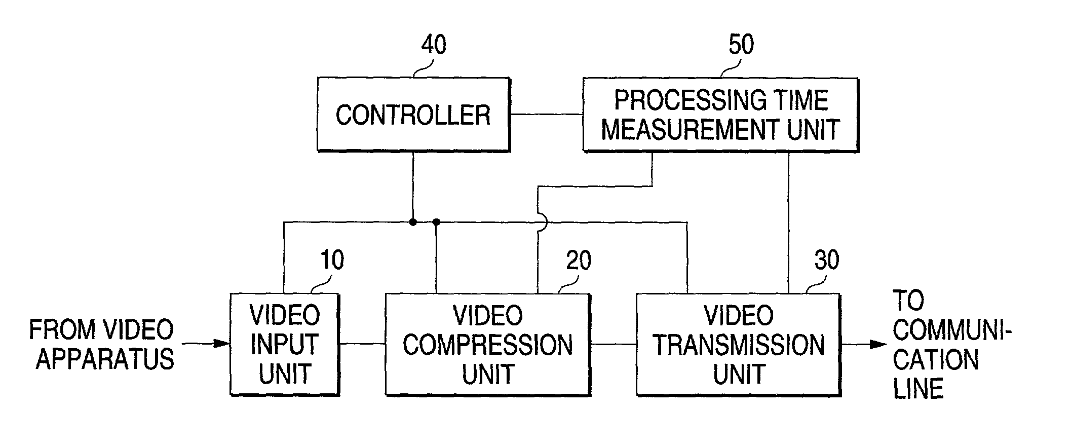
[0064]Video compression transmission apparatus according to the third embodiment of the invention allows change in at least either the compression encoding method via a video compression unit or the transmission method via a video transmission unit in the course of compression transmission. FIG. 13 is a general block diagram of video compression transmission apparatus according to the third embodiment of the invention. The video compression transmission apparatus differs from the video compression transmission apparatus in FIG. 1 in that a processing time measuring unit 50 is added.

[0065]The processing time measuring unit 50 is connected to a video compression unit 20 and a video transmission unit 30 and measures time required for video compression and video transmission per group. The compression time via the video compression unit 20 depends on the details of the picture to be compressed even when the compression ratio and compression details are the same. The transmission time vi...


PUM


Abstract

The video compression transmission apparatus comprises a video input unit for inputting pictures, a video compression unit for compressing input pictures, a video transmission unit for transmitting compressed pictures via a communication line, and a controller for controlling operation of each unit. Video compression via a video compression unit and video transmission via a video transmission unit are performed in parallel. Video compression method via the video compression unit and video transmission method via a video transmission unit are controlled by the controller so that each processing time becomes about the same.

Description

BACKGROUND OF THE INVENTION[0001]The present invention relates to a video compression transmission method and video compression transmission apparatus for compressing a digital video signal and transmitting the compressed digital video signal via a network, and in particular to a video compression transmission method and video compression transmission apparatus preferable in case compression of a digital video signal and transmission of the digital video signal requires time exceeding a normal video reproduction time.[0002]A TV program is important as a unit for news reporting. News reporting in a TV program can explain the situation of the news spot via pictures and thus enhances the reliability of the news reporting. In order to provide such news reporting, a mechanism for shooting moving pictures of the news spot for use in a program is required. Such a mechanism is here in called a news video collection system.[0003]Related art news video collection systems are roughly divided i...

Claims


Application Information

Patent Timeline
Patent Type & Authority Patents(United States)
IPC IPC(8): H04N7/12G06T9/00H04N19/00H04N19/102H04N19/117H04N19/127H04N19/134H04N19/139H04N19/14H04N19/156H04N19/177H04N19/423
CPCG06T9/00
Inventor UENOYAMA, TSUTOMUANDO, ATSUSHIHAYAKAWA, YOSHIHIRO
Owner PANASONIC CORP
Features
  • R&D
  • Intellectual Property
  • Life Sciences
  • Materials
  • Tech Scout
  • Unparalleled Data Quality
  • Higher Quality Content
  • 60% Fewer Hallucinations
Learn More