Communication apparatus and outer-loop power control method

a communication apparatus and power control technology, applied in power management, transmission monitoring, wireless communication, etc., can solve the problems of affecting the quality of the received signal in the mobile station linked to the base station, affecting the quality of the received signal in the mobile station in a stable manner, and affecting the quality of the received signal

Inactive Publication Date: 2006-07-25
FUJITSU LTD
View PDF6 Cites 19 Cited by
  • Summary
  • Abstract
  • Description
  • Claims
  • Application Information

AI Technical Summary

Benefits of technology

[0024]In accordance with the first and second aspects of the present invention, the target BLER can be attained correctly even in a case where the transmission time interval (TTI) includes a plurality of error-detecting blocks.

Problems solved by technology

In an actual mobile communications environment, however, a received signal is susceptible to interference from its own channel and from other channels owing to delayed waves ascribable to multipath fading and radio waves from other cells, and this interference has an adverse influence upon channel separation.
Further, the amount of interference sustained by a received signal varies with time owing to momentary fluctuations in reception power ascribable to multipath fading and changes in the number of users communicating simultaneously.
In an environment in which a received signal is susceptible to noise that varies with time in this fashion, it is difficult for the quality of a received signal in a mobile station linked to a base station to be maintained at a desired quality in a stable manner.
However, if the number of TrBks in the TTI is two or more and an error occurs is a plurality of TrBks, the target BLER can no longer be attained.
From the viewpoint of the nature of the error-correcting code, there are many cases where all N-number of transport blocks TrBk contain an error if an error exists in decoded data.
Thus, with the conventional schemes, a problem which arises is that the target BLER cannot be attained in a case where a plurality of error-detecting blocks (transport blocks: TrBk) are contained the transmission time interval (TTI).

Method used


Image

  • Communication apparatus and outer-loop power control method
  • Communication apparatus and outer-loop power control method
  • Communication apparatus and outer-loop power control method

Examples


first embodiment

(A) First Embodiment

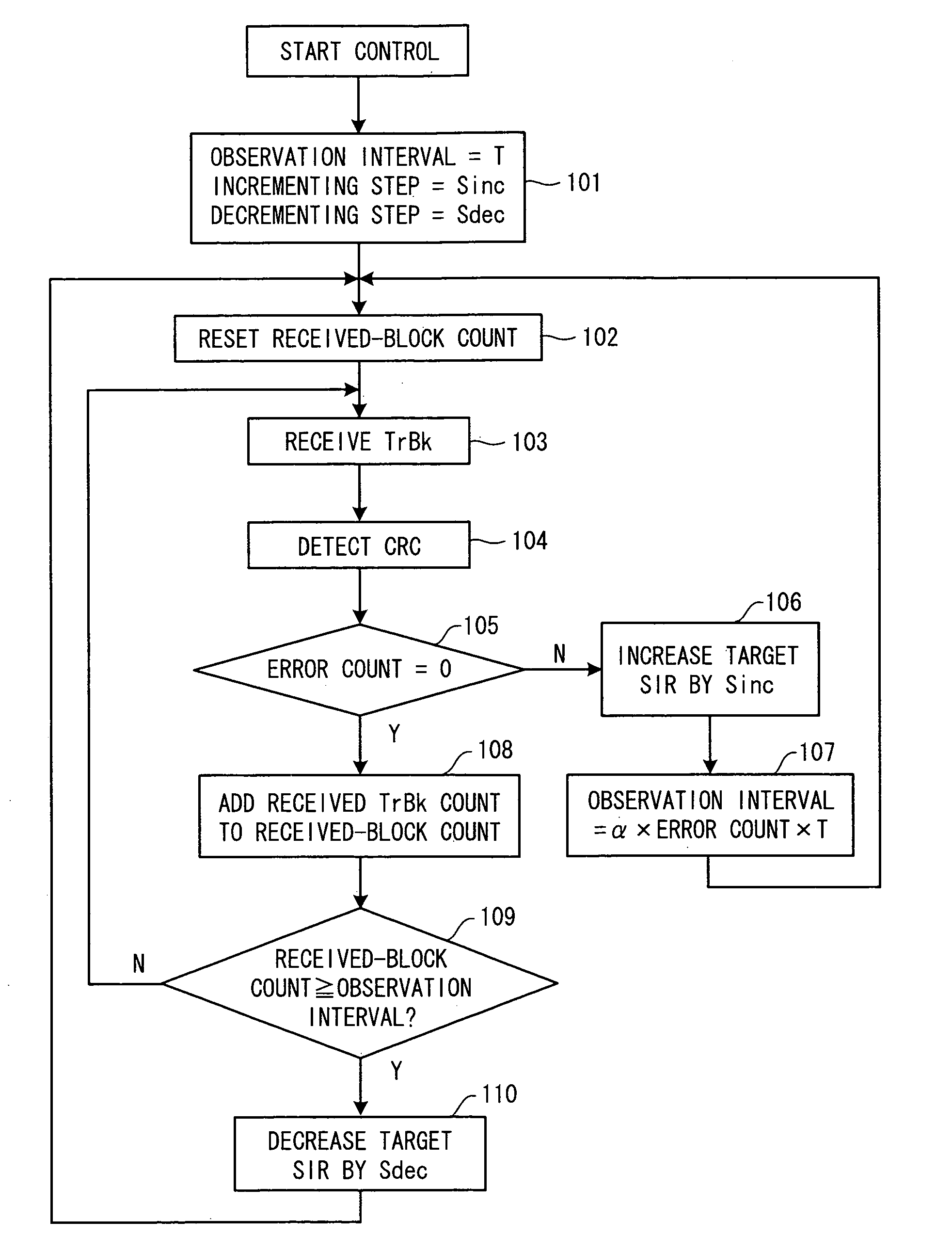
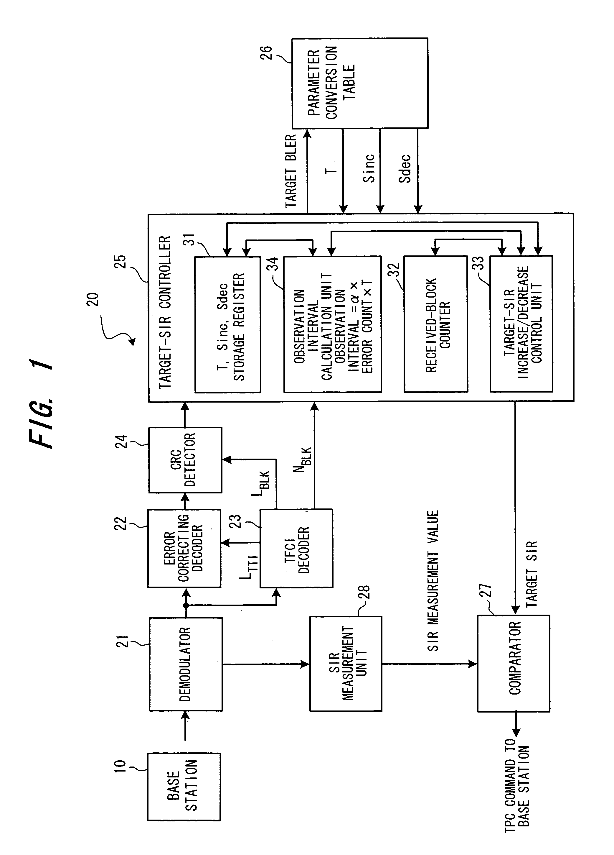
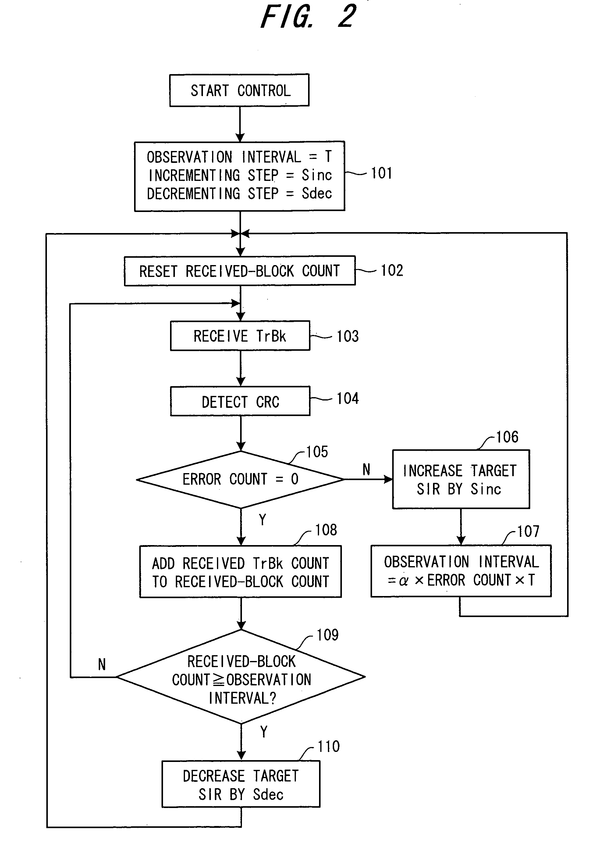
[0067]FIG. 1 is a block diagram of a first embodiment of the present invention and illustrates in detail the part of a mobile station that is for outer-loop power control. FIG. 2 is a flowchart of processing for controlling target SIR according to the first embodiment. The first embodiment is such that if error has been detected, α×Nerr×T is used instead of an initially set value T as the observation interval up to detection of the next error. More specifically, α×Nerr×T, which is the result of multiplying the set value T by a coefficient (α×Nerr) that conforms to the error count Nerr, is used as the observation interval.

[0068]In FIG. 1, a signal (a downlink signal) sent from a base station 10 is demodulated by a demodulator 21 in a mobile station 20 and then input to an error correcting decoder 22 and TFCI decoder 23. FIG. 3(a) is a diagram for describing the frame format of the downlink signal from the base station 10 to the base station 20. One frame has a dur...

second embodiment

(C) Second Embodiment

[0085]FIG. 9 is a block diagram of a second embodiment of the present invention and illustrates in detail the part of a mobile station that is for outer-loop power control. Components identical with those of the first embodiment are designated by like reference characters. FIG. 10 is a flowchart of processing for controlling target SIR according to the second embodiment. The second embodiment is such that if error has been detected, a value (=α×Nerr×Sin c) that is the result of multiplying an initially set value Sin c by the coefficient (=α×Nerr) that conforms to the error count Nerr is used instead of the initially set value Sin c as the incrementing step (amount of increase) of the target SIR.

[0086]In FIG. 9, the CRC detector 24 performs CRC error detection every transport block TrBk and the operation thereof until the error-detection result of each TrBk is input to the target-SIR controller 25 is similar to that of the first embodiment.

[0087]The target-SIR co...

third embodiment

(C) Third Embodiment

[0097]FIG. 14 is a block diagram of a third embodiment of the present invention and illustrates in detail the part of a mobile station that is for outer-loop power control. Components identical with those of the first embodiment are designated by like reference characters. FIG. 15 is a flowchart of processing for controlling target SIR according to the third embodiment. According to the third embodiment, a value resulting from division of the initially set Sdec by the coefficient (=α×Nerr) conforming to the error count Nerr that prevailed the last time an error was detected is used instead of Sdec as the decrementing step (amount of decrease) of the target SIR that prevails if a single error has not been detected during the time of the observation interval.

[0098]In FIG. 14, the CRC detector 24 performs CRC error detection every transport block TrBk and the operation thereof until the error-detection result of each TrBk is input to the target-SIR controller 25 is ...


PUM


Abstract

An outer-loop power control method and a communication apparatus having an outer-loop power control function for increasing target SIR if an error is detected in a block-error observation interval and decreasing target SIR if not a single error is detected in the block-error observation interval. At least one of the block-error observation interval, an incrementing step for when target SIR is increased and a decrementing step for when target SIR is decreased is varied based upon the number of erroneous blocks among error-detecting blocks contained in a transmission time interval TTI.

Description

CROSS-REFERENCE TO RELATED APPLICATION[0001]The present application is a continuation of International Application No. PCT / JP02 / 03413 which was filed on Apr. 5, 2002, which is herein incorporated by reference.BACKGROUND OF THE INVENTION[0002]This invention relates to a communication apparatus having an outer-loop power control function and to an outer-loop power control method. More particularly, the invention relates to a communication apparatus having an outer-loop power control function and to an outer-loop power control method for increasing target SIR if an error is detected in a block-error observation interval and decreasing target SIR if not a single error is detected in the block-error observation interval.[0003]In CDMA mobile communications, multiple channels are distinguished from one another by spreading codes that are assigned to the channels, whereby a plurality of channels perform communication sharing a single frequency band. In an actual mobile communications enviro...

Claims


Application Information

Patent Timeline
Patent Type & Authority Patents(United States)
IPC IPC(8): H04B7/00H04Q7/20H04B7/005H04W52/12H04W52/24
CPCH04W52/12H04W52/248H04W52/241
Inventor YANO, TETSUYAOBUCHI, KAZUHISA
Owner FUJITSU LTD
Why Eureka
Try Eureka