Culture tray for the rooting of young plants

a technology for growing plants and trays, applied in the field of trays, can solve the problems of difficult removal of earth, damage to plants when being taken out of multiple pots, and difficulty in lifting out young plants from multiple pots, and achieve the effect of easy lateral forcing of plant bales and easy lifting

Inactive Publication Date: 2006-08-01
DUMMEN GRP BV
View PDF10 Cites 8 Cited by
  • Summary
  • Abstract
  • Description
  • Claims
  • Application Information

AI Technical Summary

Benefits of technology

[0012]To enable discretional spacing of the young plants in one row it is intended to use single-walled or multi-walled, especially double-walled, webs as partitions. By varying the double wall distances, i.e. between two spaced-apart webs, adaptation to each plant type is possible. A double-walled arrangement of webs can typically be achieved in a plant row by placing between every two webs a cross strip which may slope down to each web and direct the water into the plant rooms.
[0013]Another embodiment of the invention is characterised by connecting the partition webs by a single-piece bottom ledge. So the bottom ledge carries a number of the partition webs which separate the plant spaces from one another. The bottom ledge and the webs so create a plant row skeleton with a plurality of spaces for young plants which are easy to lift out of the culture tray channel or, in a special embodiment of the invention, can be pushed out sideways. Pushing out sideways, for which a machine may be used, removes the entire plant row out of the culture tray, so that the spaces, because of their special shapes, allow easy lateral forcing of the plant bales out of the plant row. Taking out the young plants with their bales is also practicable with the use of a machine in a further automation of the work process.
[0014]To enable surplus ...

Problems solved by technology

It must be regarded as a drawback of the well-known embodiment of a culture tray that lifting the young plants out of the multiple pots may be difficult after the roots have grown.
This may typically be due to the fact that the earth is difficult to remove from the multiple pots because of the ...

Method used


Image

  • Culture tray for the rooting of young plants
  • Culture tray for the rooting of young plants
  • Culture tray for the rooting of young plants

Examples


Embodiment Construction

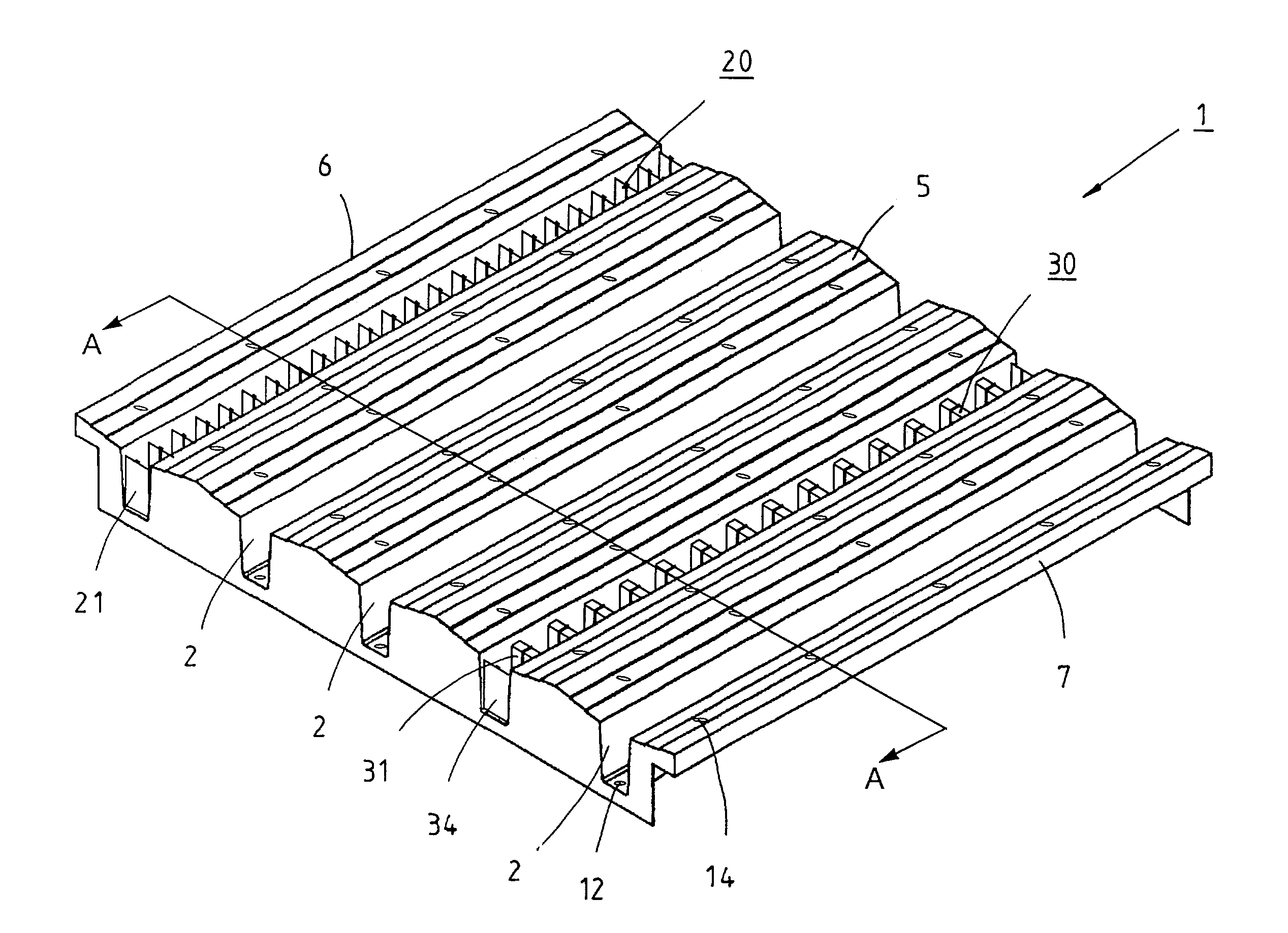
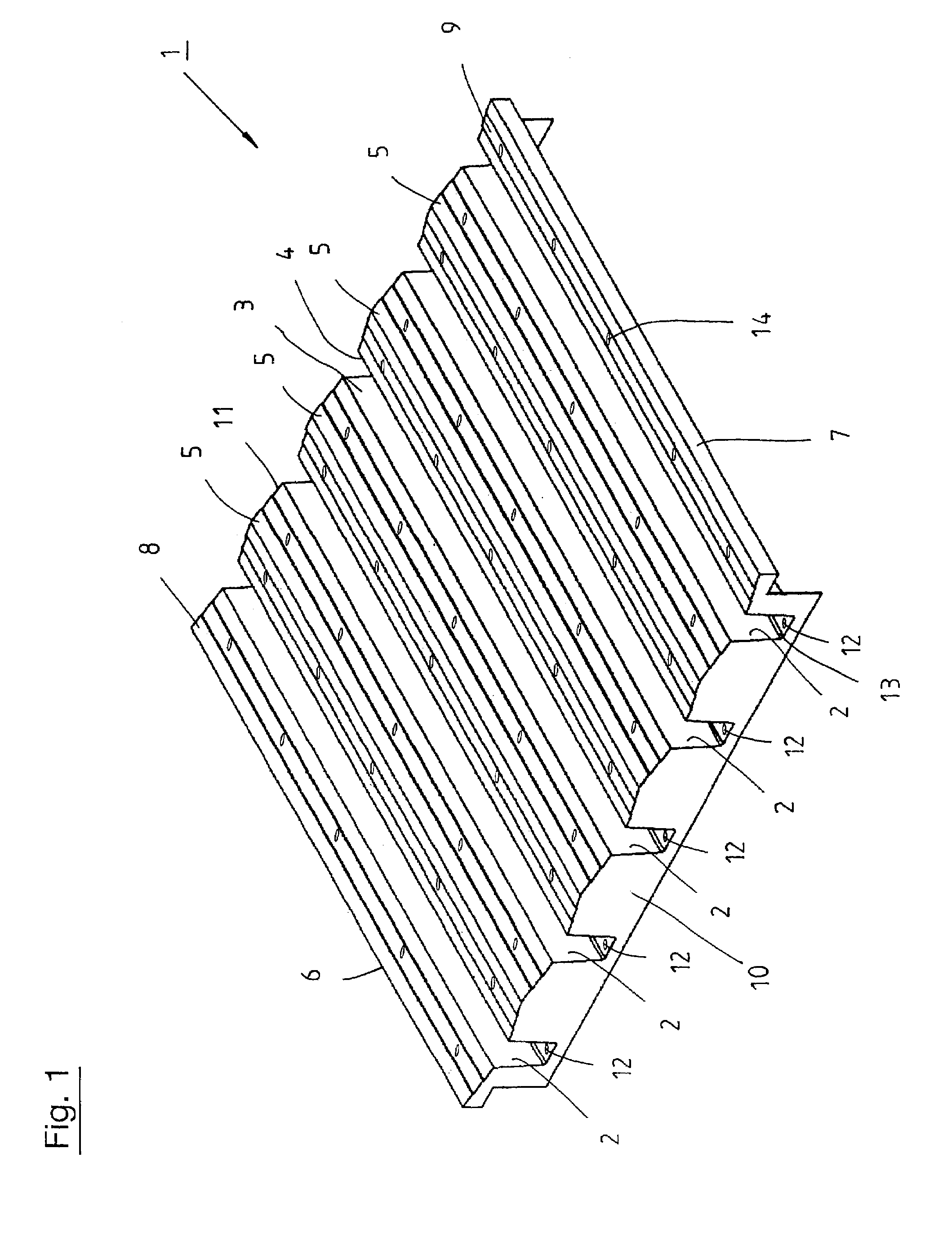
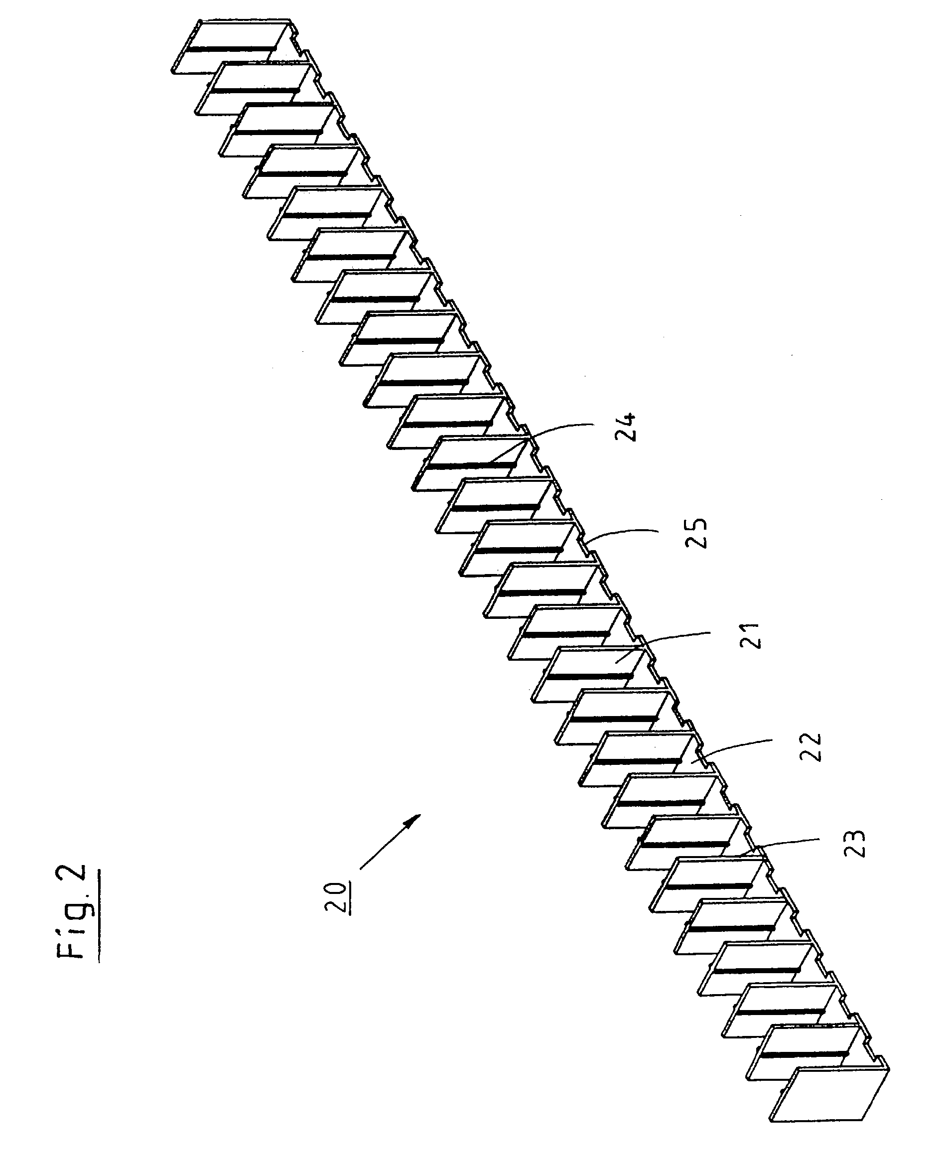
[0025]FIG. 1, being a perspective view, shows a culture tray 1 according to the invention, which can be equipped with row skeletons per FIG. 2 or 3. The culture tray 1 is basically a deep drawn plastic component which has transverse channels 2 in equidistant arrangement. It is, of course, possible to make different culture trays 1 in which the distances between the channels vary. Channels 2 have two sidewalls 3, 4 and are open towards the rim of culture tray 1. A roof-shaped elevation 5 can be seen between every two channels. Its structure is stepped in the embodiment shown. Of course, other structures are practicable provided it is made certain that the water intended for irrigation can flow down sideways into the channels 2. Each end tray 6, 7 of the culture tray 1 has one half-side elevation 8, 9 which coresponds to the shape of elevation 5 when the two culture trays 1 have been assembled. The culture tray 1 is stiffened only by means of an end closing wall 10, 11 in a manner to ...


PUM


Abstract

A culture tray, in particular for the rooting of young plants, includes channels that run in parallel and at predefinable distances and serve to accommodate young plants. To enable removal of individual young plants preferably without harming them and to enable relatively economical consumption of water for the young plants the space for each young plant is limited by the sidewalls of the channel and across the longitudinal direction of the channel by partition webs. This arrangement will, in particular, ensure that the water is directly supplied to each plant space and, moreover, that the plants can be pushed sideways out of the culture tray by pushing out of the culture tray the web and ledge skeletons, and the plants are easy to take out, because there are then no sidewalls. The embodiment of the culture tray warrants uniform moistening of all existing plant spaces and ensures that even those plants receive enough water that are, for example, partly covered by large leaves of adjacent plants, since the water draining down the elevations flows into each individual plant space.

Description

CROSS REFERENCE TO RELATED APPLICATIONS[0001]Applicant claims priority under 35 U.S.C. 119 of German Application No. 102 11 723.3 filed Mar. 18, 2002.BACKGROUND OF THE INVENTION[0002]1. Field of the Invention[0003]This invention relates to a culture tray, in particular for the rooting of young plants, with parallelled and mutually spaced channels for the accommodation of the young plants.[0004]2. The Prior Art[0005]Culture trays of these types are employed in greenhouses in great numbers for the rooting of young plants, the greenhouses offering a climate favourable for the desired culture plants and an appropriate moisture of the air. It is especially advantageous in this connection, if the rate of water flow used for the control of the humidity of the air and for the watering of the young plants can be kept constant within narrow limits and the flow is still sufficient to provide each young plant with enough water.[0006]The German patent specification DE 198 44 020 typically relate...

Claims


Application Information

Patent Timeline
IPC IPC(8): A01G9/02A01G9/00A01G9/10
CPCA01G9/104A01G9/0295
Inventor DUMMEN, MARGA
Owner DUMMEN GRP BV
Why Eureka
Try Eureka