Manually held dental flossers

a technology of flossing holder and flossing ring, which is applied in the field of tooth flossing, can solve the problems of inability to floss daily, inconvenient use, and inability to adhere to flossing daily, and achieve the effect of reducing spring force and improving leverage

Inactive Publication Date: 2006-08-01
KOSSAK MICHAEL
View PDF53 Cites 30 Cited by
  • Summary
  • Abstract
  • Description
  • Claims
  • Application Information

AI Technical Summary

Benefits of technology

[0016]In a preferred embodiment, the tension arm of the second tensioning element is in constant engagement between two of the supply spool mounting post ratchet teeth to lockingly engage the mounting post and prevent supply spool rotation when the trigger is not being depressed to advance floss. To maintain supply spool lock-up during trigger deactivation, a portion of the trigger within the housing and opposite the depressed trigger end is adapted to pivot into abutting contact with the distal end of the tension arm to thereby prevent supply spool mounting post rotation in the unwinding direction.
[0017]Still with reference to the preferred embodiment, the trigger actuating mechanism is neither directly spring biased nor integrally formed with an actuating pawl at one end thereof as is the cas...

Problems solved by technology

Otherwise, continued use of the same exposed piece will likely result in transference of plaque and bacteria from one interproximal space to another.
However, only the most conscientious individuals adhere to such a strict schedule.
This is because flossing is generally regarded as an unpleasant experience since there are a number of problems which occur during flossing which result in a failure to floss daily.
One such problem, for example, is that it can be difficult and painful for the individual to wrap the floss tightly enough around the fingers to maintain the needed tension, and then to unwrap and rewrap the used piece to expose a fresh piece to floss the next interproximal space.
It is also unpleasant to handle the wet, odorous, used floss and to wrap such material about the fingers of the hands.
Additionally, gagging may occur during flossing and it can be painful to hold one's mouth open long enough and wide enough to floss every tooth, particularly rearwardly located teeth.
Furthermore, it is often difficult to work with fingers from both hands in the mouth and the force applied to get the floss between the teeth can be excessive.
Often, the floss snaps into the gum causing it to bleed.
Furthermore, although floss is relatively inexpensive, quite a bit is used in a single cleaning and there is considerable wast...

Method used


Image

  • Manually held dental flossers
  • Manually held dental flossers
  • Manually held dental flossers

Examples


Embodiment Construction

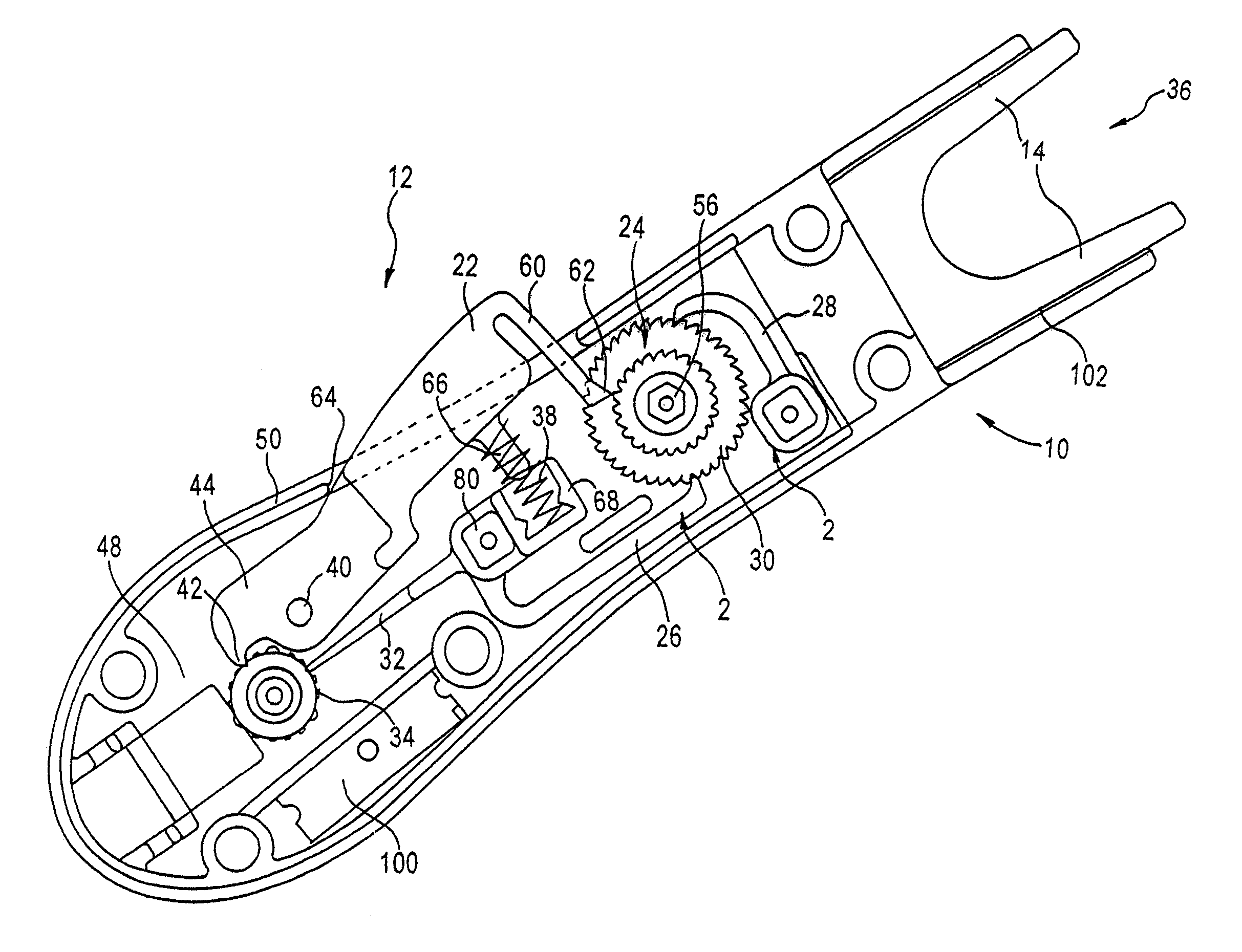
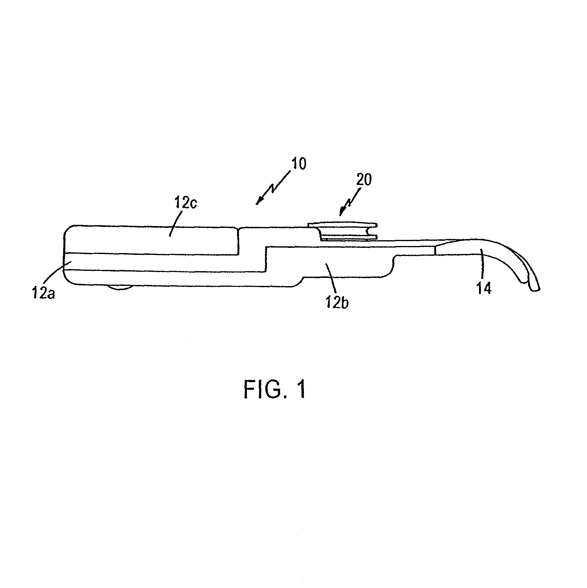
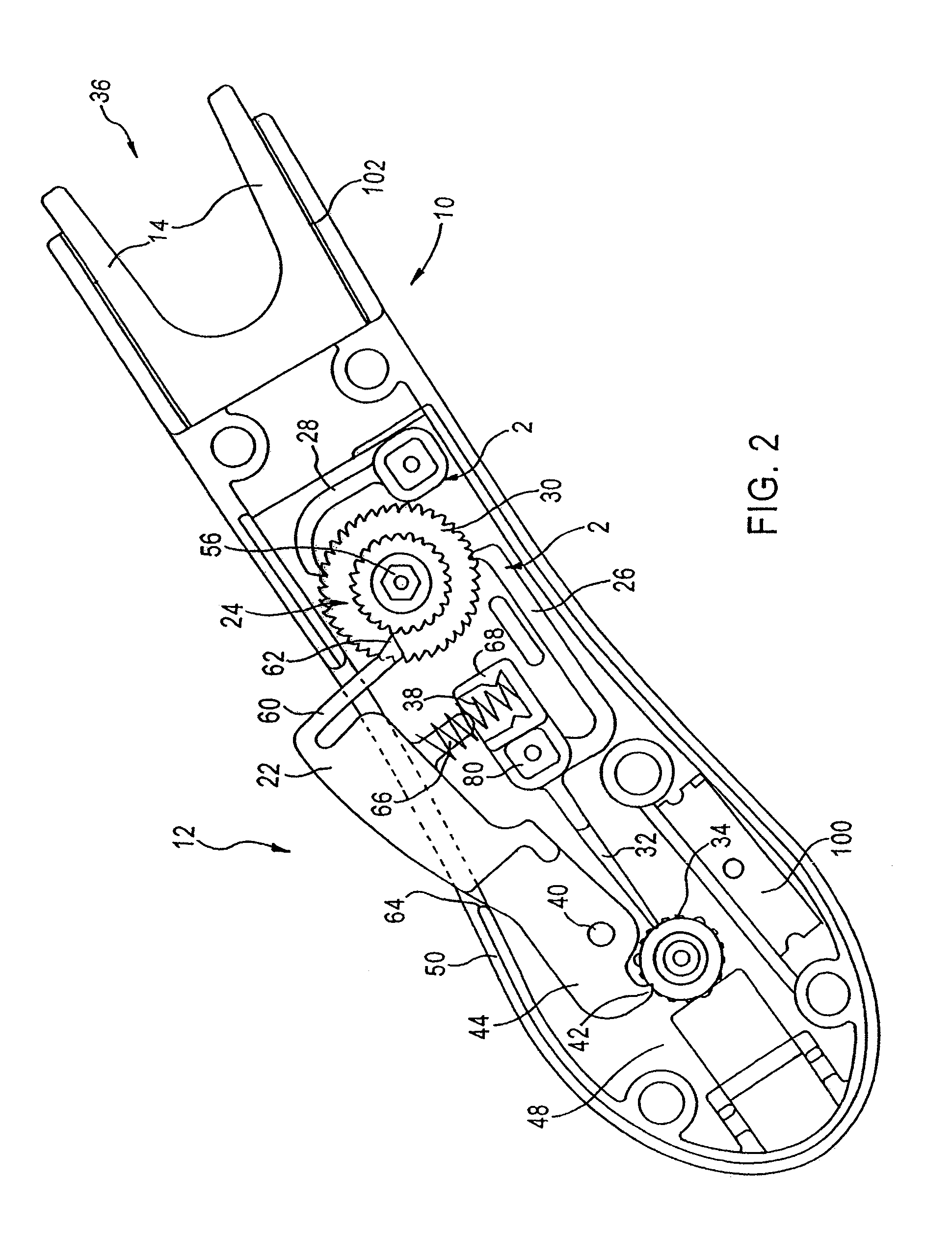
[0031]Referring to FIGS. 1 and 2, there is disclosed a manual dental flosser 10 having a handle or body portion 12 formed from a top housing 12a and a bottom housing 12b from which bottom housing a pair of fork arms 14 project forwardly in laterally spaced relationship to each other. The handle 12 supports a floss supply spool 16 normally covered with a snap-on cover 12c. Supply spool 16 is uniquely mounted to a supply spool mounting post 18, and a take-up spool 20 is mounted forwardly (i.e. closer to the fork arms 14) of the floss supply spool in the novel manner described below. Manually depressing a trigger 22 projecting from a side of handle 12 is operable to partially rotate an input drive ratchet 24, co-rotatably mounted to the take-up spool 20, which in turn co-rotates the take-up spool in a counter clockwise direction. The take-up spool 20 is rotatable in one direction only, i.e. to wind used floss, and is preferably located advantageously above top housing 12a. Undesired ro...


PUM


Abstract

A dental flossing device is characterized by a flossing circuit comprised of a flossing supply spool and a take-up spool mounted to a housing. The floss feeds from the supply spool along a pair of prongs forming a fork extension of the handle and is stretched across the prongs and appropriately tensioned to be inserted into a users mouth for flossing. To maintain tension, a pair of ratchet pawls are jointly engageable with a ratchet mounted for co-rotation with the take-up spool. The pawls are offset relative to the ratchet teeth to ensure appropriate tension. Tension on the supply spool side of the flosser is achieved with a tension arm in constant engagement with tension teeth co-rotatably mounted with the spool. When a floss advancing trigger is not depressed, a brake pawl formed at one end of the trigger is spring biased into locking engagement with these teeth while the tension arm assures proper tension on the supply side. In an alternative preferred embodiment, only one tensioning ratchet pawl engages the ratchet mounted for co-rotation with the take-up spool. A different ratchet pawl, mounted to one end of a ratchet arm pivotally secured to the flosser housing beneath the ratchet, is engaged by the trigger to drivingly contact the ratchet to rotate the take-up spool. In this latter embodiment, the brake pawl is replaced with a projection formed on the trigger that is adapted to engage the supply spool tensioning ratchet to lock the ratchet in the released position of the trigger to prevent supply spool rotation and maintain the floss circuit in a tight condition.

Description

RELATED APPLICATIONS[0001]This application is directed to inventions that are improvements over flossing equipment disclosed in U.S. Pat. No. 5,678,578, to Kossak et. al. This application is a continuation-in-part of U.S. application Ser. No. 09 / 689,626 filed Oct. 13, 2000 now abandoned.TECHNICAL FIELD[0002]The present invention relates generally to tooth flossing and, more particularly, to manual floss holders for use in the avoidance in periodontal diseases.BACKGROUND ART[0003]Flossing is the only effective method for cleaning between teeth to remove plaque buildup which is the primary causative agent of gingivitis, periodontitis, and tooth decay. The most commonly used method of flossing is to strip a large piece of floss off a dispenser, about one and one half to two feet, wrap it around one's fingers, and to then work an exposed piece of floss between the fingers of both hands up and down against the tooth surfaces defining the interproximal spaces between the teeth. Ideally, a...

Claims


Application Information

Patent Timeline
IPC IPC(8): A61C15/00A61C15/04
CPCA61C15/046
Inventor KOSSAK, MICHAELTOMELLINI, DALITAKOTOWSKI, PAUL
Owner KOSSAK MICHAEL
Why Eureka
Try Eureka