Device for applying a substance, in particular a cosmetic, and its method of manufacture

a technology for cosmetics and devices, applied in the direction of hand devices, cleaning devices, packaging goods, etc., can solve the problem of difficult to deposit an appropriate thickness, and achieve the effect of increasing the quantity of substances and allowing the application of flexible members by the application member

Inactive Publication Date: 2006-08-01
LOREAL SA
View PDF14 Cites 6 Cited by
  • Summary
  • Abstract
  • Description
  • Claims
  • Application Information

AI Technical Summary

Benefits of technology

[0010]By means of the present invention, the surface of the element used for application can be made more comfortable and more suitable for picking up an increased quantity of substance. The fibers may form a covering of down extending over more than one-fourth, or indeed more than one-half, e.g. three-fourths of the surface area used for application purposes. The element may be elastically deformable and / or compressible. The element may be a felt or a foam. Additionally, the felt or foam may be made of a single material. The term “felt” is used herein to mean a fiber structure comprising filaments that are tangled in all directions. Such a structure can be relatively compact.
[0011]At least a fraction of the fibers may be formed by the walls of the cells that have burst. Such a covering of down may lead to softness in the application comparable to that provided by flocking, while avoiding the drawbacks thereof.
[0013]The foam may include craters in its surface. The craters may be of a depth of not less than 0.4 millimeters (mm) and possibly not less than 0.7 mm. The craters may even have a depth of not less than 1.3 mm or even not less than 1.5 mm. Such craters may be obtained by removing the walls from a group of cells, the group comprising five to fifteen cells. The craters make it possible for the foam to contain at its surface a quantity of substance that is greater than the quantity possible when the foam has been cut by means of a sharp tool and has not been subjected to subsequent treatment. The fibers may extend from around each crater.
[0017]The applicator member may comprise a first foam element fixed to a second foam element so as to form an applicator member associated with a support, or in a variant a sponge that is independent of any support. Between them, the two elements may define an internal cavity, for example a cavity filled with air, thus giving the applicator member greater flexibility during application. The two elements may present surface states that are either substantially identical, or else differ from one another.
[0018]The applicator member may be fixed by means of a central region to a support and it may present a free peripheral region, e.g. capable of flexing when pressed against the surface onto which the substance is to be deposited. The surface of the applicator member used for application may be outwardly concave. Such a shape making it possible to increase the quantity of substance with which the applicator member can pick up.
[0021]In another of its aspects, the present invention provides a method of manufacturing an applicator device in which a surface of the device includes a fibrous or cellular element. The surface, which is to be used as an applicator surface, is treated in such a manner as to form fibers from the material of the element. The fibers thus projecting from the surface of the element. Such a surface state may be obtained in particular by subjecting the surface of the element to abrasive treatment. This makes it possible with a foam to burst the walls of the cells present at the surface of the foam, thereby creating down and craters.

Problems solved by technology

In addition, it has been found that by using foams shaped by cutting with a sharp tool, the walls of the cells present at the surface of the foam have a tendency to scrape the substance on the skin, thus making it difficult to deposit an appropriate thickness thereof.

Method used


Image

  • Device for applying a substance, in particular a cosmetic, and its method of manufacture
  • Device for applying a substance, in particular a cosmetic, and its method of manufacture
  • Device for applying a substance, in particular a cosmetic, and its method of manufacture

Examples


Embodiment Construction

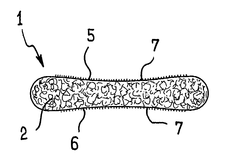
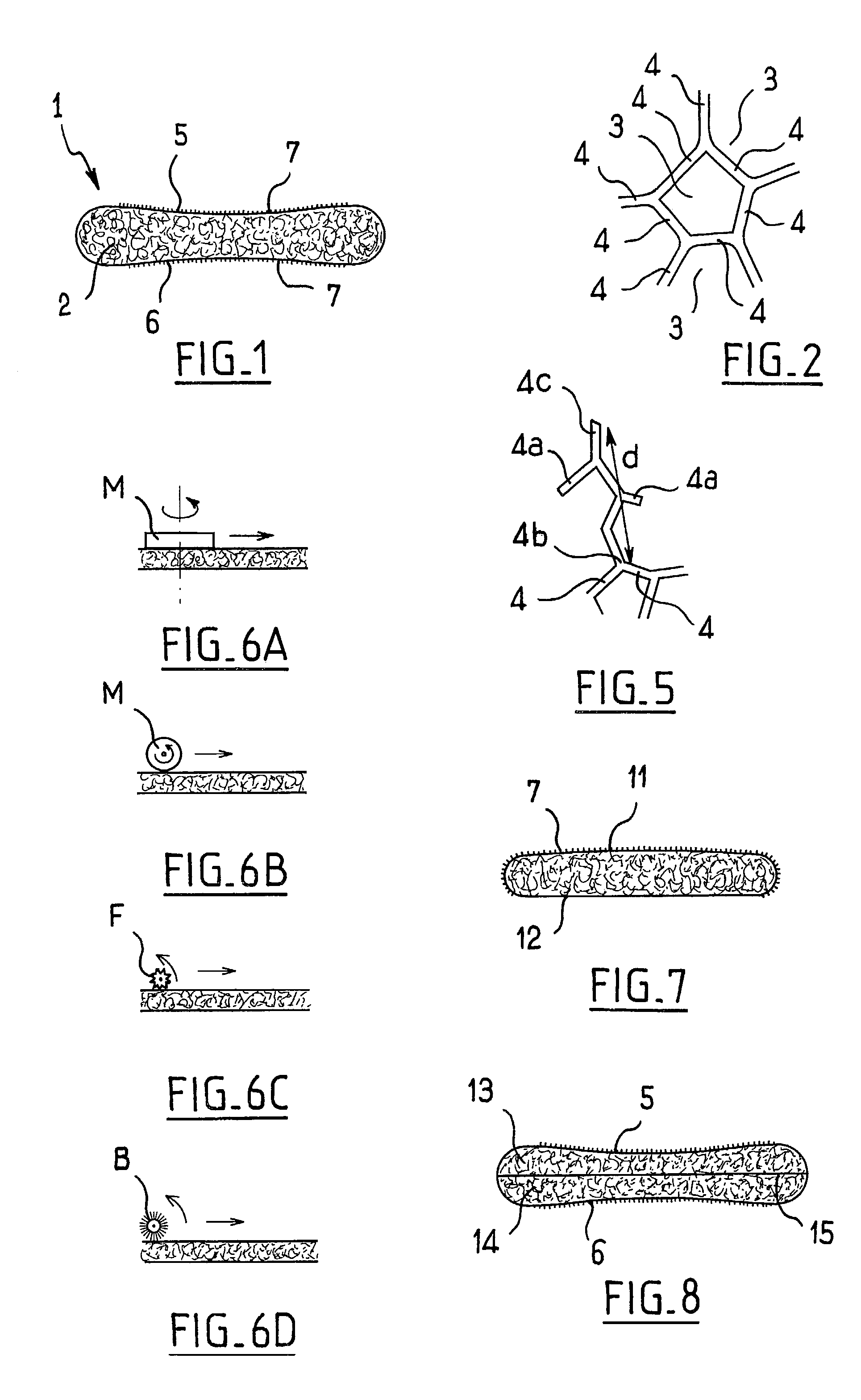
[0037]FIG. 1 shows a sponge 1 for use in applying a powder on the skin.

[0038]In the example shown, the sponge 1 is constituted by a block of open-celled foam, e.g., a flexible polyurethane foam. In a variant, the sponge may be made of felt.

[0039]FIG. 2 details that each cell 3 is formed by a plurality of interconnected thread-like walls 4 extending in multiple directions. By way of example, each cell may comprise a succession of four or five walls 4 each of which is substantially rectilinear and together forming a loop.

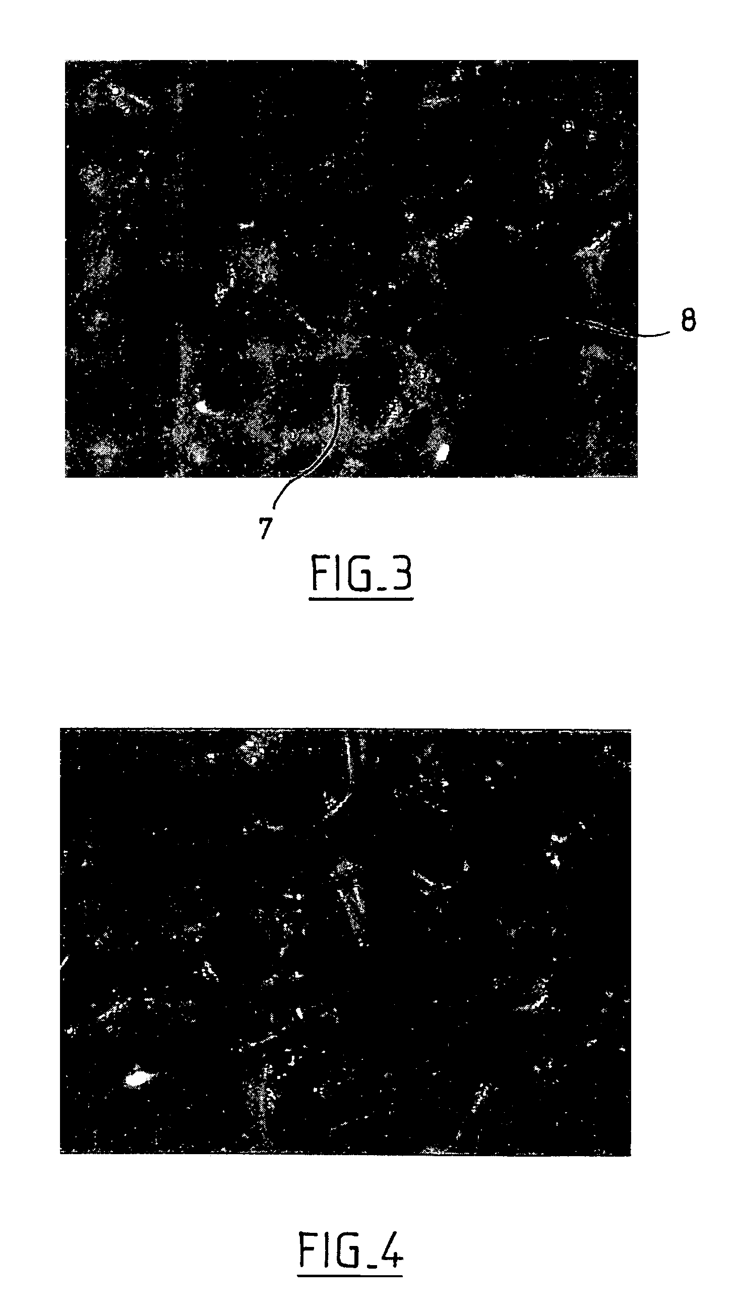
[0040]The sponge 1 shown in FIG. 1 has two main opposite faces 5 and 6 that are both slightly concave away from the exterior of the sponge 1. Each face 5 and 6 has received an abrasive treatment in order to form down 7 and craters 8 in their respective surfaces. The down 7 is formed by the shredded walls of cells, as can be seen in the photograph of FIG. 3. The surface state of the faces 5 and 6 is thus different from the surface state that would be obtained by cuttin...


PUM

PropertyMeasurementUnit
depthaaaaaaaaaa
depthaaaaaaaaaa
depthaaaaaaaaaa

Abstract

A device for applying a substance, the device including an applicator member having at least one of a fibrous and cellular element. The element defines a surface for applying the substance. At least a portion of the surface includes projecting fibers. The projecting fibers are attached to a portion of the element. The portion of the element and the fibers may be made out of the same material.

Description

CROSS REFERENCE TO RELATED APPLICATIONS[0001]This application claims the benefit of PCT Application No. 02 06089, France, filed May 17, 2002 and U.S. Application No. 60 / 391,044 filed Jun. 25, 2002, the disclosures of which are incorporated by reference herein.BACKGROUND OF THE INVENTION[0002]The present invention relates to devices for applying a substance, in particular a cosmetic, and their methods of manufacture.[0003]The term “cosmetic” is used to mean a substance as defined in EEC Council Directive 96 / 35 of Jun. 14, 1993, amending for the sixth time EEC Directive 76 / 768.[0004]Numerous applicator devices are known comprising an applicator member made of foam having a surface that is used for applying substance on the skin, for example a powder, a lotion, or a cream.[0005]In order to increase the uniformity of the resulting makeup, or to improve comfort of application, the foam is sometimes covered in flocking. For some substances, the presence of the flocking can reduce the quan...

Claims


Application Information

Patent Timeline
Patent Type & Authority Patents(United States)
IPC IPC(8): B43K5/00B05C21/00A45D33/00A45D33/34A45D34/04
CPCA45D34/04A45D33/34A45D33/006A45D2200/1018
Inventor GUERET, JEAN-LOUIS
Owner LOREAL SA
Why Eureka
Try Eureka