Providing mechanical support for modular interconnect systems

a technology of mechanical support and modular connectors, applied in the direction of coupling devices, two-part coupling devices, electrical apparatus, etc., can solve the problems of increasing connector demands and affecting the reliability of connections, and achieve the effect of improving the mechanical support of modular connector systems

Inactive Publication Date: 2006-08-01
IBM CORP
View PDF17 Cites 7 Cited by
  • Summary
  • Abstract
  • Description
  • Claims
  • Application Information

AI Technical Summary

Benefits of technology

[0005]It is, therefore, a principle object of this invention to provide improved mechanical support for modular connector systems.
[0006]It is another object of the invention to provide an improved modular connector system in which a first modular connector assembly can be moved into mating relationship with a second modular connector assembly with a reduced degree of tilting between the modular connector assemblies.

Problems solved by technology

The increasing complexity of computers and other electrical equipment brings with it increasing demands on connector systems that are used with printed wiring boards in the equipment.
This causes stress on the connector assemblies and the PWCs on which they are mounted, and can also cause a degree of misalignment of the blades themselves and thereby undermine the reliability of the connections.

Method used


Image

  • Providing mechanical support for modular interconnect systems
  • Providing mechanical support for modular interconnect systems
  • Providing mechanical support for modular interconnect systems

Examples


first embodiment

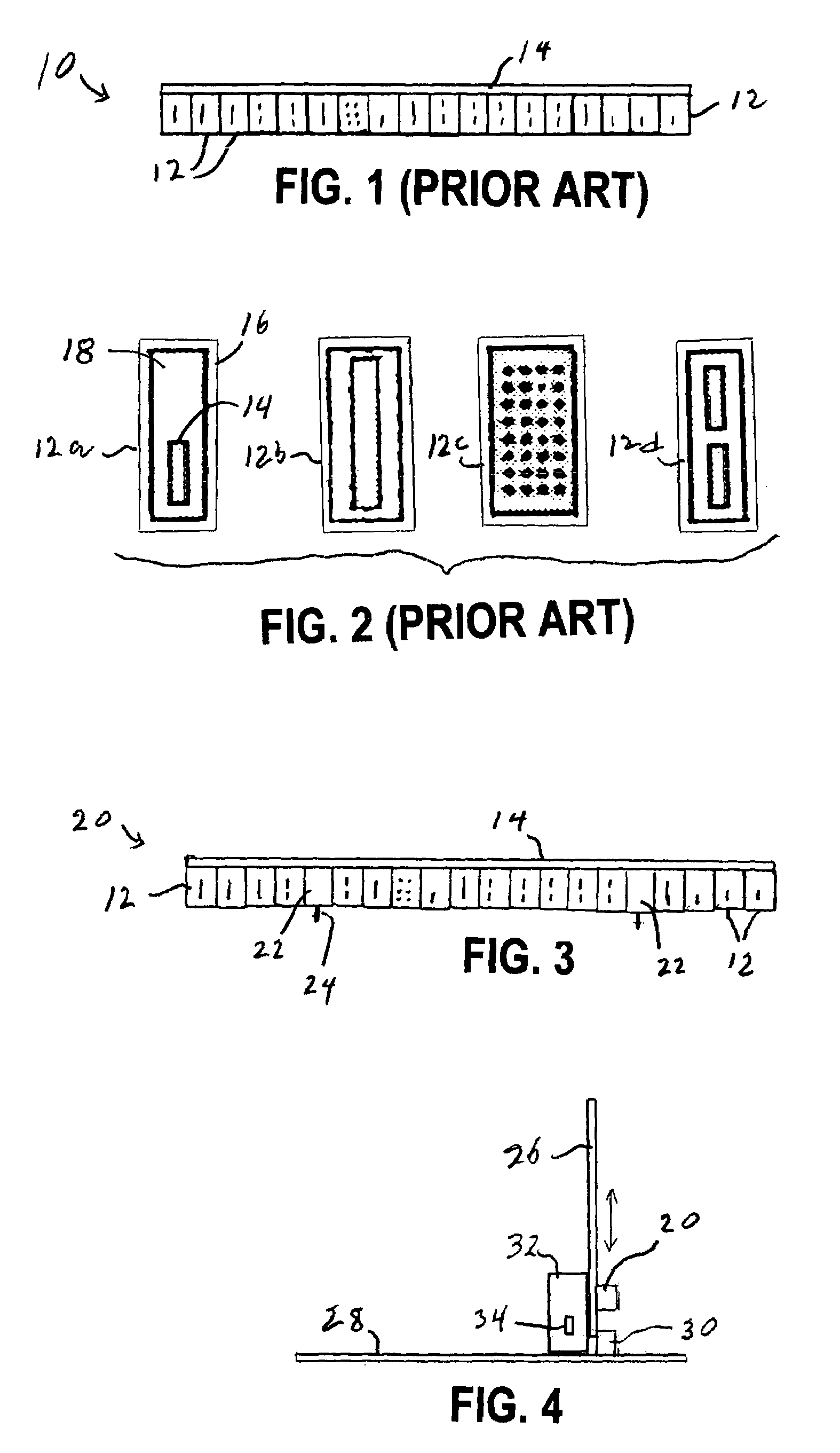
[0018]the present invention will now be described with reference to FIGS. 3 and 4. In FIG. 3, a connector assembly 20 includes a number of connector modules 12 that are mounted in a row on a support such as an organizer 14. Interspersed among the connector modules 12 are a pair of actuator modules 22 that are also mounted on the organizer 14. The actuator modules 22 have engagement studs 24 that project outward in a direction perpendicular to the blades of the connector modules 12.

[0019]In FIG. 4, the connector 20 is electrically connected to wiring or a printed wiring board (PWC) 26. For the sake of convenient illustration, the PWC 26 is shown without the integrated circuits and so forth that it would ordinarily carry. Likewise, a PWC 28 is shown in FIG. 4 without the electrical components that would normally be connected to it.

[0020]A connector assembly 30 is connected to wiring on the PWC 28. The connector assembly 20 has male-type modules 12, so the assembly 30 includes female-t...

second embodiment

[0023]the present invention will now be described with reference to FIGS. 5–8.

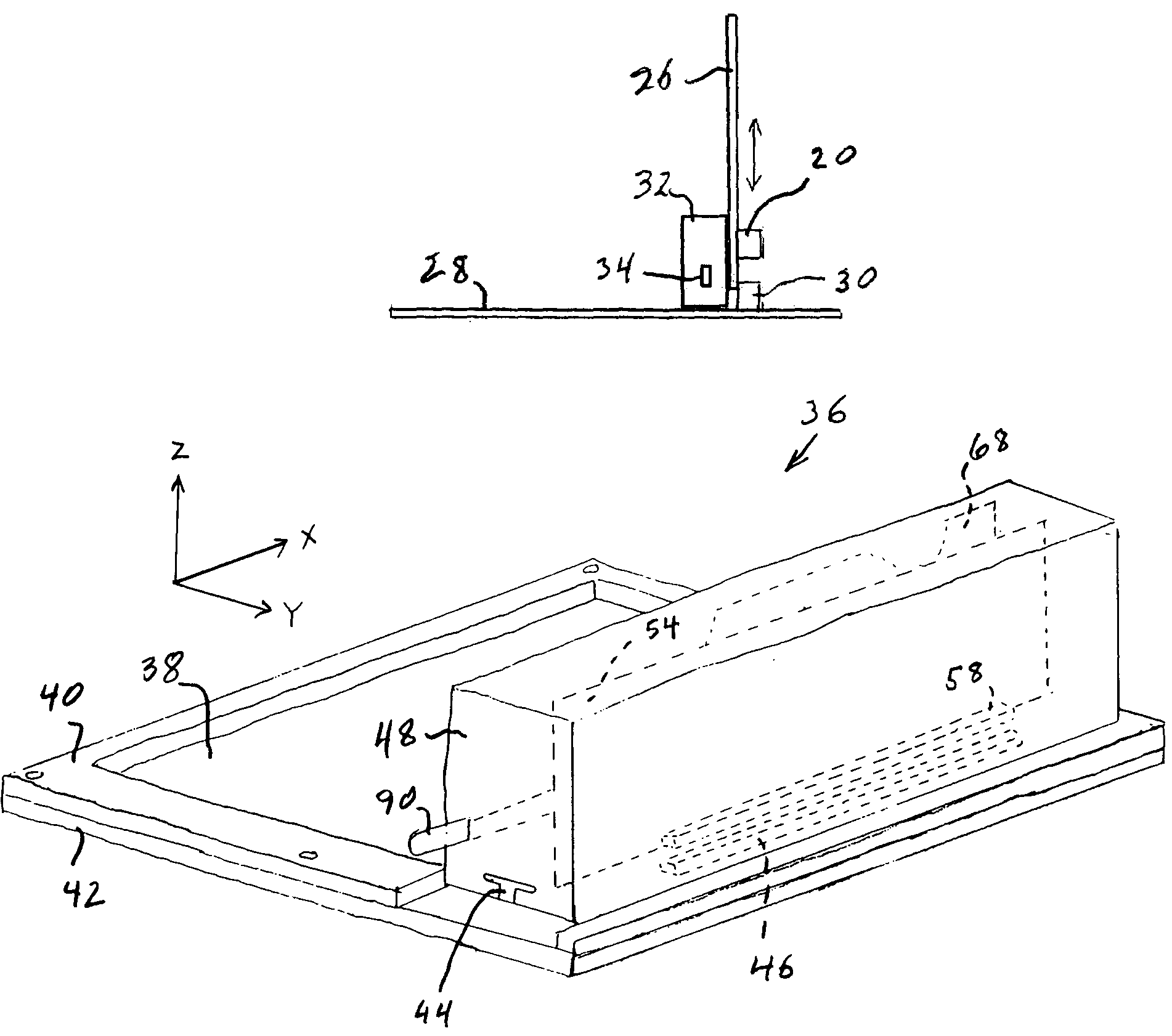
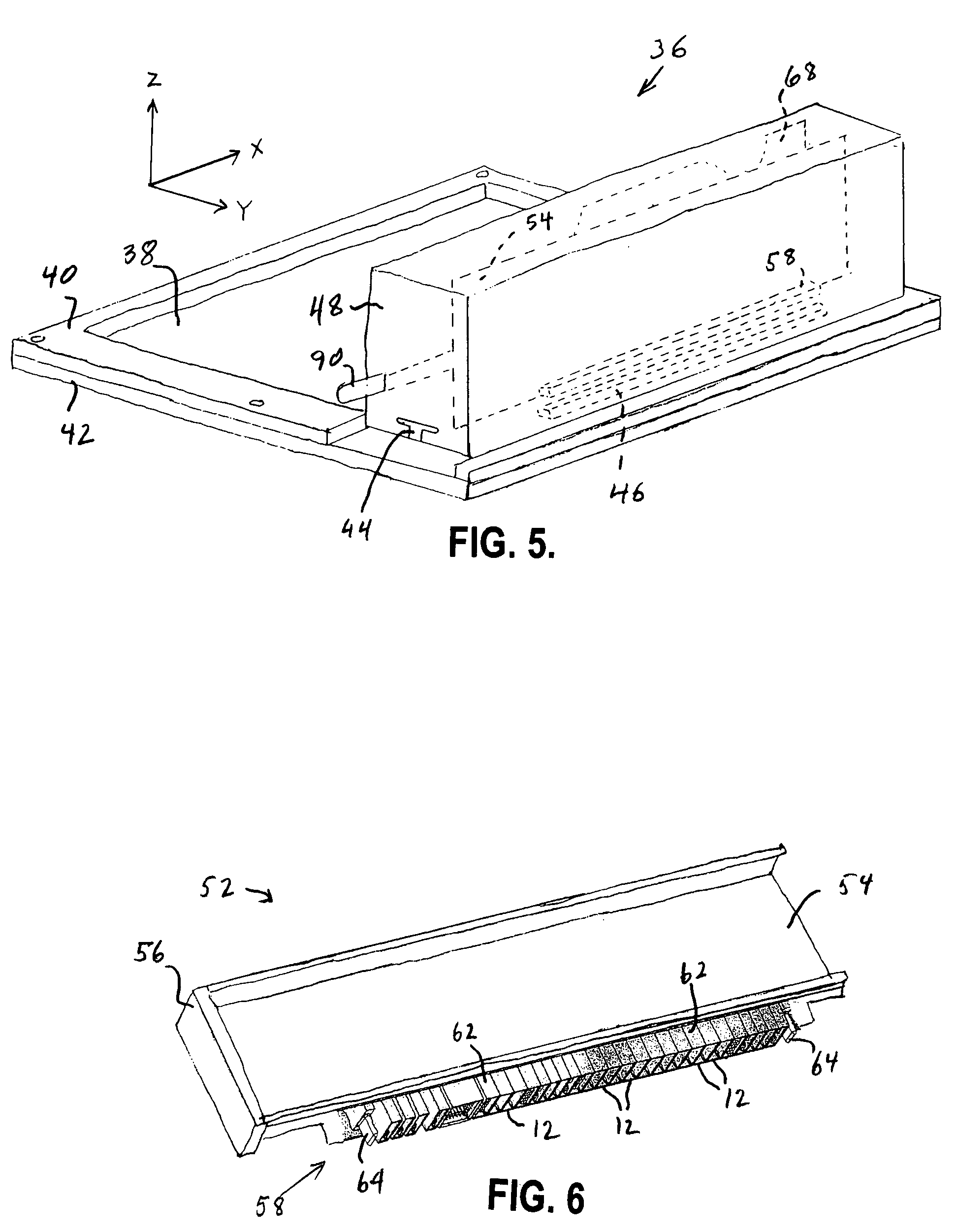
[0024]FIG. 5 illustrates a processor unit book 36 having a PWC 38 on which electrical components (not illustrated) are mounted. The PWC 38 is supported between an upper framing member 40 and a lower framing member 42. The member 40 has an opening, and a guide rail 44 is exposed through this opening. The guide rail 44 is mounted on the lower framing member 44 and extends in the X direction. A lower connector assembly 46 is electrically connected to wiring on the PWC 38.

[0025]A direct current adaptor unit 48 has an elongated opening (not numbered) that conforms in shape to the guide rail 44. This permits the unit 48 to be inserted onto the guide rail 44 and moved in the X direction to the position illustrated in FIG. 5.

[0026]The unit 48 includes a component 52, which is shown in FIG. 6. The component 52 includes a PWC 54 that is mounted on a frame 56. HV blades of a connector assembly 58 convey a power suppl...


PUM


Abstract

A connector system includes a first connector assembly that is electrically connected to wiring on a first printed wiring board and a second connector assembly that is electrically connected to wiring on a second printed wiring board. Each connector assembly includes a number of connector modules that are joined together in a predetermined array such as a row. In one of the connector assemblies, the row also includes one or more actuation modules. The actuation module or modules are engaged by an actuator mechanism to force the connector assemblies into mating engagement or to draw them apart.

Description

BACKGROUND OF THE INVENTION[0001]The present invention is directed to electrical connector systems, and more particularly to connector systems that are employed to provide electrical connections with circuitry on printed wiring boards.[0002]The increasing complexity of computers and other electrical equipment brings with it increasing demands on connector systems that are used with printed wiring boards in the equipment. Many signals may need to be conveyed between different printed wiring boards (which will hereafter be called PWCs), and considerable power may be drawn by the circuitry on the PWCs. The power demands of the PWCs and the number of signal connections that are needed typically differ from PWC to PWC.[0003]FIG. 1 schematically illustrates a connector assembly 10 that includes a number of connector modules 12 which are mounted on an organizer 14. Different types of modules 12 are commercially available (for example, from Molex Inc., having an office at 2222 Wellington Co...

Claims


Application Information

Patent Timeline
Patent Type & Authority Patents(United States)
IPC IPC(8): H01R9/22
CPCH01R12/52H01R23/68H01R12/727
Inventor BRODSKY, WILLIAM LOUISSCANLON, MICHAEL F.TOROK, JOHN G.
Owner IBM CORP
Why Eureka
Try Eureka