Method for connecting an electric actuator to a printed circuit board

a technology of printed circuit board and solderless connection, which is applied in the direction of automatic control devices, measurement/indication equipments, contact member manufacturing, etc., can solve the problems of reducing the melting temperature of tin-based soldering paste, obsolete and dangerous techniques, and the use of soldering pastes. achieve good mechanical support of the actuator, easy to solder on the printed circuit, and high speed

Active Publication Date: 2011-05-10
SONCEBOZ
View PDF8 Cites 6 Cited by
  • Summary
  • Abstract
  • Description
  • Claims
  • Application Information

AI Technical Summary

Benefits of technology

[0013]The present invention provides a solution to these problems and proposes, for this purpose, an industrial method for connecting the actuator to the printed circuit on a large scale, inexpensively, in an automated fashion and at a high speed, not requiring soldering of the actuator and guaranteeing good mechanical support of the actuator on the printed circuit. In a first step, the method consists of a simple, inexpensive SMD-type transfer of a specific metal contact, especially developed for implementing the invention. These metal contacts have an open contact zone which can be made by stamping, shearing or any other equivalent method. They can be delivered in various formats according to the current state of the art, for example the following methods can be cited: individually in bulk, in strips adapted to the placement machines, in “tape & reel” where each contacts is placed individually in a plastic support, etc. These contacts are, in a preferable but non-limiting manner, made from steel and have a thickness of typically around 0.1 mm. They generally have a coating that makes them easier to solder on the printed circuit. The mix that allows the soldering of the contact is previously deposited at the location of the contact on the circuit. Once the contacts are deposited, the circuit is placed in a furnace with a defined variable temperature profile. The electrical contacts and the other components are therefore soldered during this operation.
[0014]In a second stage, once the printed circuit is soldered with all the SMD components (metal contacts, LEDs, monitoring electronics, etc.), the actuator can be connected to the circuit, without soldering and with no temperature-related trauma and without requiring any considerable insertion force.
[0017]This specific shape makes it possible to crimp the connection pins and guarantee the electrical contact. Grooves present on the connection pins make it possible, in addition, to maintain the connection rigid. However, these grooves are not essential, since the connection of the tabs is guaranteed by the physical contact between the two elements.
[0019]In a preferred embodiment of the invention, the printed circuit had pads, which is to say tinned zones, with a substantially square shape. They are designed to receive the substantially square metal contacts, with a side length preferably comprised between 0.8 times and 1 time the side length of said pad. This shape and geometric ratio guarantee self-centering of the metal contact on the pad during the soldering step. This results in the positioning of the metal contacts being completely precise and guarantees an optimal orientation of the opening in relation to the connection pin.

Problems solved by technology

However, changes in environmental standards are rendering these techniques obsolete and dangerous for the environment, since they still require the use of lead, which reduces the melting temperature in tin-based soldering pastes (typically to 180° C.).
The new soldering pastes used, almost entirely made from tin, therefore have the disadvantage of requiring higher melting temperatures (around 220-230° C.
), which can damage the electric actuators and / or certain fragile components mounted on the printed circuit.
These solutions have the disadvantage of being expensive and of often comprising a thermoplastic element designed to support the tulip connectors.
In addition, while the electrical connection is guaranteed, the mechanical support is far from perfect, which can be detrimental to applications such as the micromotors used on motor vehicle dashboards.
In fact, the printed circuit+actuator assembly is subjected to potentially considerable vibrations and there is a real need for good mechanical support.
This increases the production cost and adds an extra step to the assembly of the actuator.
This solution is practical since it does away with the need to solder the components, but is also has certain disadvantage: the force of insertion on the printed circuit is considerable, which can damage said circuit, and the connectors and the drill holes on the printed circuit must have accurate manufacturing tolerances in order to ensure sufficient mechanical support.
The connection stress is high, creating constraints that are detrimental to the printed circuit.

Method used


Image

  • Method for connecting an electric actuator to a printed circuit board
  • Method for connecting an electric actuator to a printed circuit board
  • Method for connecting an electric actuator to a printed circuit board

Examples


first embodiment

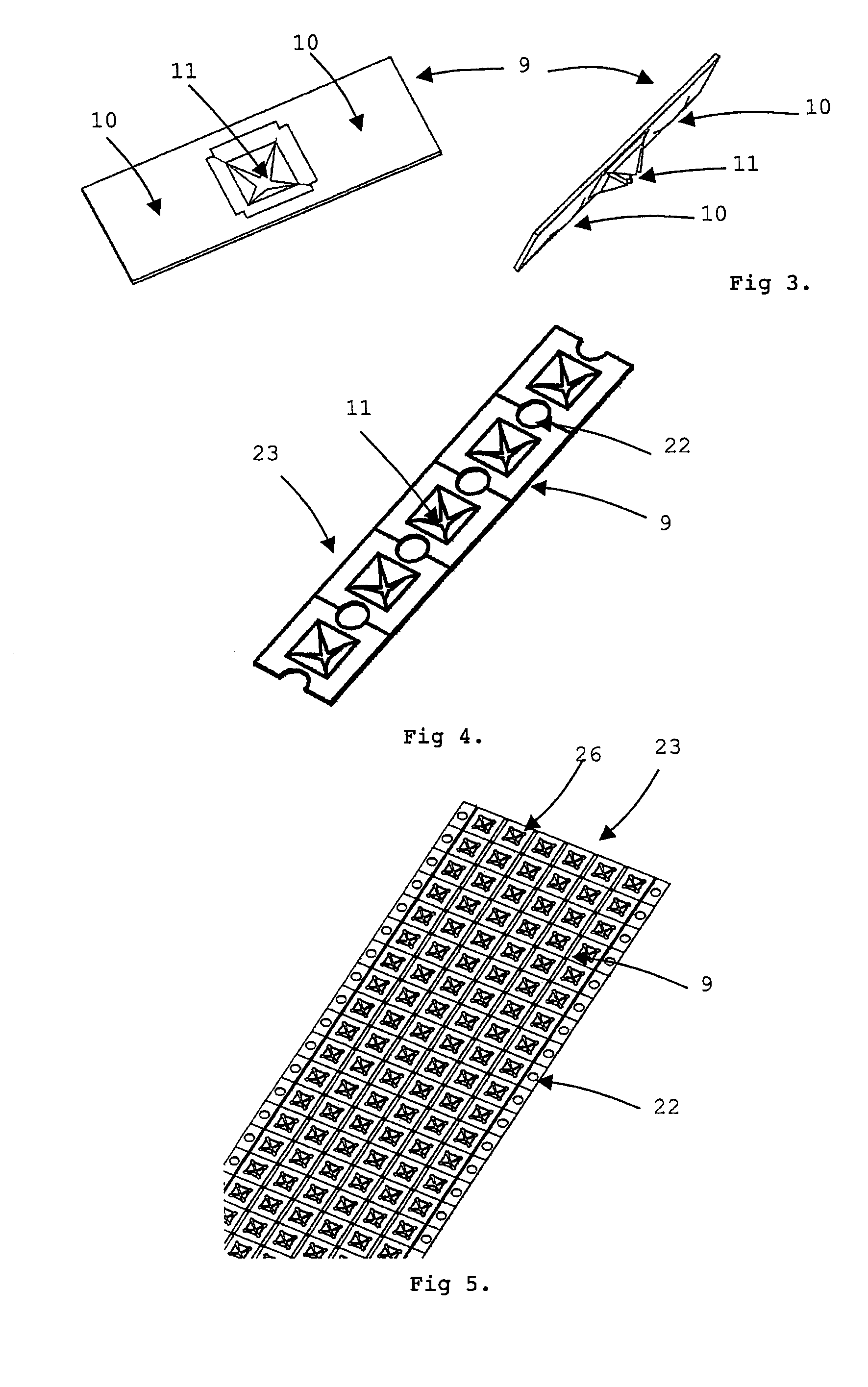
[0052]FIG. 4 shows the metal contacts (9) in a strip (23) in the invention and prior to use. They advantageously comprise, in a non-limiting manner, a cutting zone (22) which allows the cutting tool to handle the strip (23) and move it forward. The electrical contact zone (11) is visible. It can be made by stamping, as shown in FIG. 6, which is to say that the material is lifted in order to form the contact zone (11). It can also be made by shearing, as shown in FIG. 7, which is to say by cutting the material with no loss. The choice of one method or the other will depend on the production imperatives.

second embodiment

[0053]FIG. 5 shows the metal contacts (9) in a strip (23) in the invention and prior to use. In this embodiment, in which several rows (26) are positioned next to one another, it is possible to create cutting zones (22) which can be used by the cutting tool to handle the strip (23) and move it forwards.

[0054]In a preferred embodiment, the metal contact (9) has a substantially square shape, with the side length marked A.

[0055]In both cases, the opening zone defines a diameter D in which the contact zone is capable of folding.

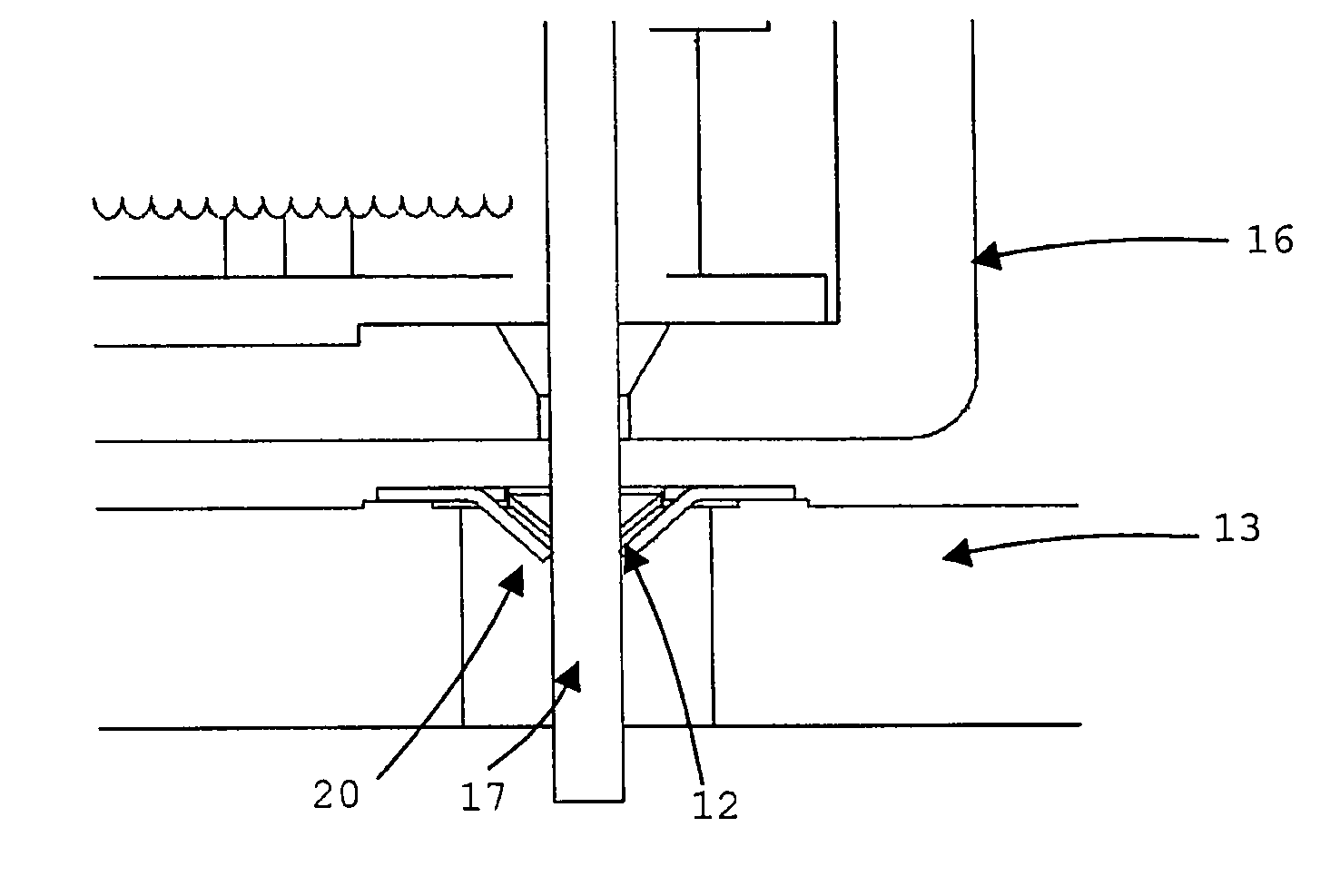
[0056]This metal contact (9) is designed to be placed on a tinned pad or zone (24) of the printed circuit (13), as shown in FIG. 8, which advantageously has a substantially square shape in which the side length is marked as B. When soldering the metal contact using a SMD-type method (by reflow, for example) and in order to guarantee self-centering of the metal contact (9) on the pad (24), as shown in FIG. 9, the side length A must advantageously be comprised betw...


PUM

PropertyMeasurementUnit
melting temperatureaaaaaaaaaa
melting temperaturesaaaaaaaaaa
thicknessaaaaaaaaaa

Abstract

A method of connecting an electric actuator to a printed circuit by metal contacts having an open contact zone. The metal contacts are soldered to the printed circuit using an SMD-type automated method performed at a high speed and at a high temperature, and the electrical connection pins of the actuator can be mechanically connected to the metal contacts without soldering by butting the contact zone of the metal contacts against the connection pins of the actuator once the connection pins have been inserted through the contact zone.

Description

BACKGROUND OF THE INVENTION[0001]I. Field of the Invention[0002]The present invention relates to a method for solderless connection of an electric actuator to a printed circuit, mainly for applications on motor vehicle dashboards.[0003]II. Description of Related Art[0004]The traditional methods of soldering electronic components onto printed circuits, whether through-hole mounted or surface mounted devices (SMD), are already known in the prior art. For example, the so-called wave method allows soldering of through-hole mounted components placed on the printed circuit by means of a wave of tin and lead which comes into contact with the printed circuit, and thus to solder the components. Another example is the so-called reflow method, which consists of passing the printed circuit, on which the components are pre-positioned with a mix of tin and lead (soldering paste), through a series of furnaces with different temperature levels. This method is currently the most widespread for solde...

Claims


Application Information

Patent Timeline
Patent Type & Authority Patents(United States)
IPC IPC(8): H01R9/00H01R12/00
CPCH01R12/57H05K3/326H05K3/306H05K3/4015H05K2201/1059Y10T29/5122Y10T29/49128Y10T29/49204Y10T29/49165Y10T29/49153Y10T29/4913H01R12/718H01R43/02
Inventor SIGG, DANIELZUPPIGER-LACHAT, CORINNE
Owner SONCEBOZ
Why Eureka
Try Eureka