Damper for a vehicle torque transferring assembly

a technology of torque transfer assembly and damper, which is applied in the direction of shock absorbers, mechanical actuated clutches, mechanical apparatus, etc., can solve the problems of inability to combine with most internal dampers, high cost of plugs, and inability to reduce only a narrow band of frequencies, so as to achieve easy assembly and reduce noise and vibration.

Inactive Publication Date: 2006-08-01
AUTOMOTIVE COMPONENTS HOLDINGS
View PDF23 Cites 25 Cited by
  • Summary
  • Abstract
  • Description
  • Claims
  • Application Information

AI Technical Summary

Benefits of technology

[0007]In view of the above, the present invention relates to a lightweight easily assembled and cost efficient damper for reducing noise and vibration in torque transferring assemblies. The torque transferring assembly for a vehicle includes a tubular shaft having an inner surface defining an elongated cavity and a damper retained within the cavity. The damper is formed from a material having a density less than 1.4 lb / ft3, and includes an outer surface that is resiliently biased against the inner surface of the tubular shaft when installed, to prevent movement of the damper relative to the tubular shaft. The damper generally has a density greater than 1.0 lb / ft3 and an uninstalled density of approximately 1.2 lb / ft3.

Problems solved by technology

Yet another problem with tubular shafts in torque transferring assemblies is that they produce undesirable noise when rocks or other debris forcefully impact the tubular shaft during vehicle operation.
Another problem with most corrugated liners is that they cannot be combined with most internal dampers that reduce noise and vibration produced or transmitted by the torque transferring assembly.
These plugs typically reduce only a narrow band of frequencies are expensive and require increased assembly time to ensure correct installation at the specific node.
Another problem with these plugs or internal dampers is that they generally are not capable of reducing impact noise.
While these materials span the length of the tubular shaft to provide dampening against impact noises, they do not reduce noise and vibrations produced or transmitted over a wide enough range of frequencies to an acceptable level.

Method used


Image

  • Damper for a vehicle torque transferring assembly
  • Damper for a vehicle torque transferring assembly
  • Damper for a vehicle torque transferring assembly

Examples


first embodiment

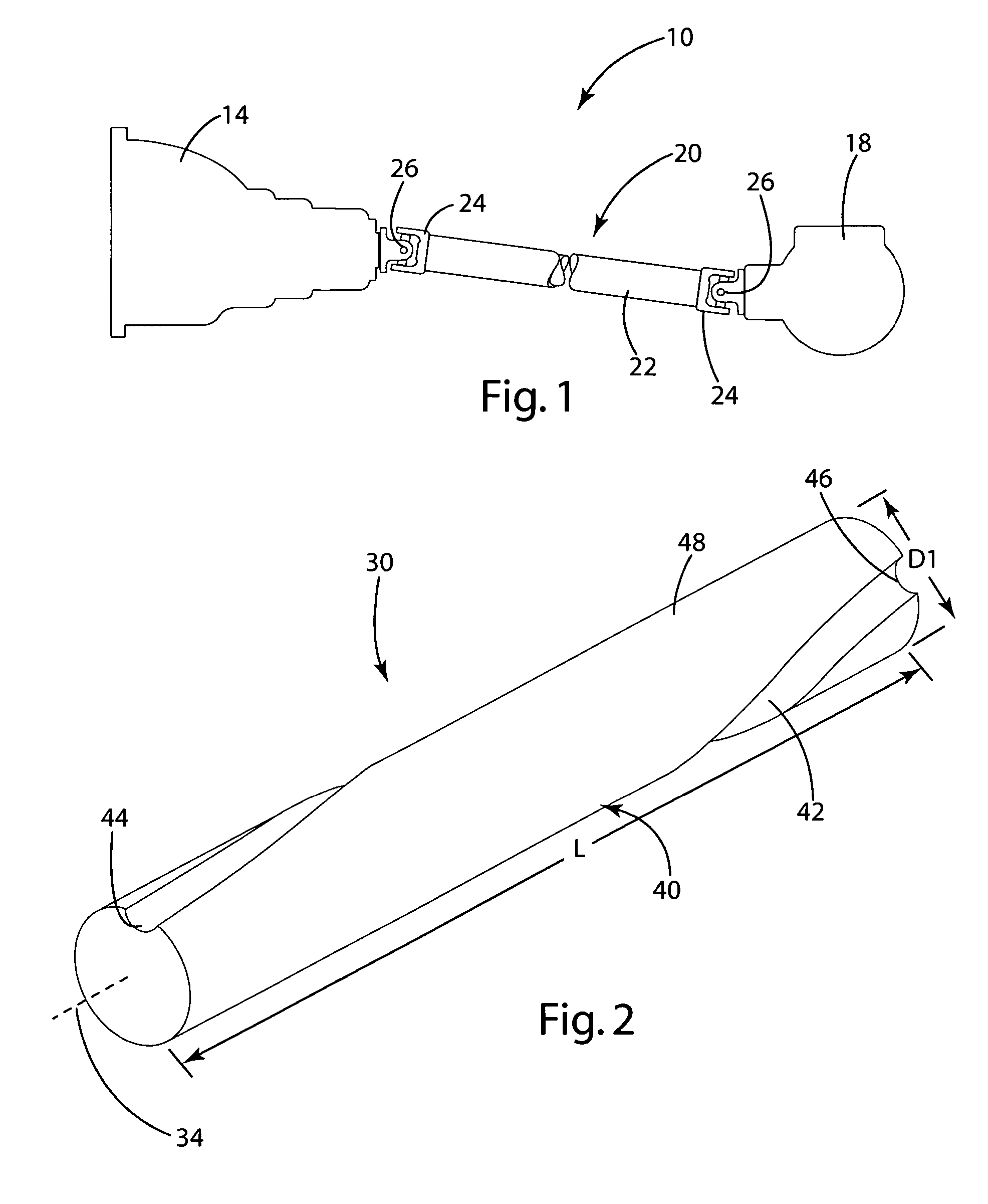
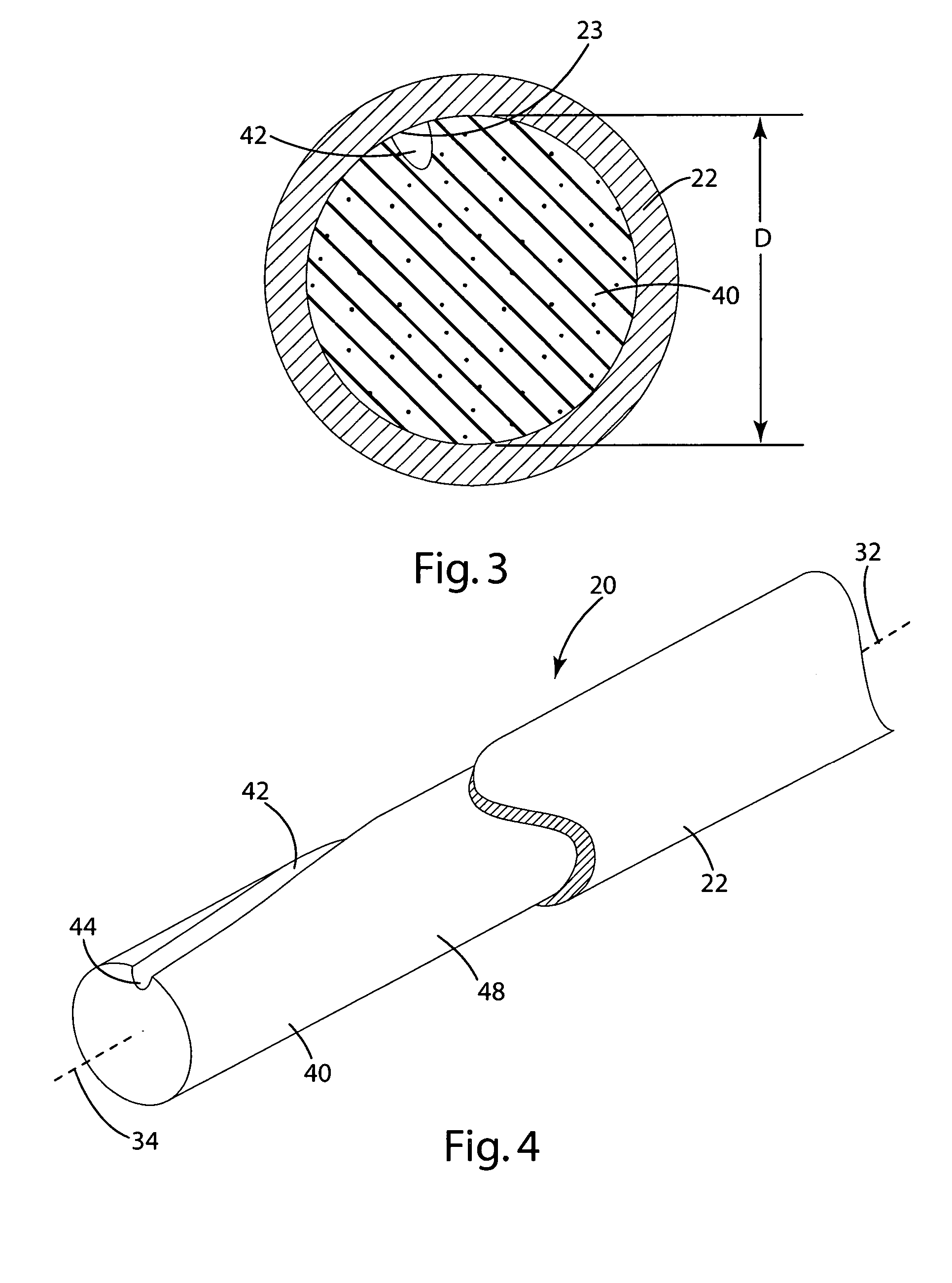
[0028]In the first embodiment, the damper 30 is illustrated in FIGS. 3 and 4 as being formed from a cylindrical foam structure 40 referred to hereinafter as a foam damper 40. The foam damper 40 generally matches the shape of the tubular shaft and is illustrated in FIG. 2 as being cylindrical. The foam damper 40 includes a channel 42 extending from a first outlet 44 defined by one end to a second outlet 46 defined by the opposing end. In the illustrated embodiment, the outlets 44,46 are radially displaced about the longitudinal axis 34, with the channel 42 located therebetween forming a helix on the outside surface of the foam damper 40. To provide an acceptable level of dampening, it is helpful if the first outlet 44 is not arranged linearly along the longitudinal axis 34 with the second outlet 46. Inventors have found that a range of 30° to 330° radial displacement of the outlets provides improved noise and vibration absorption over outlets that are aligned along the linear axis. I...

second embodiment

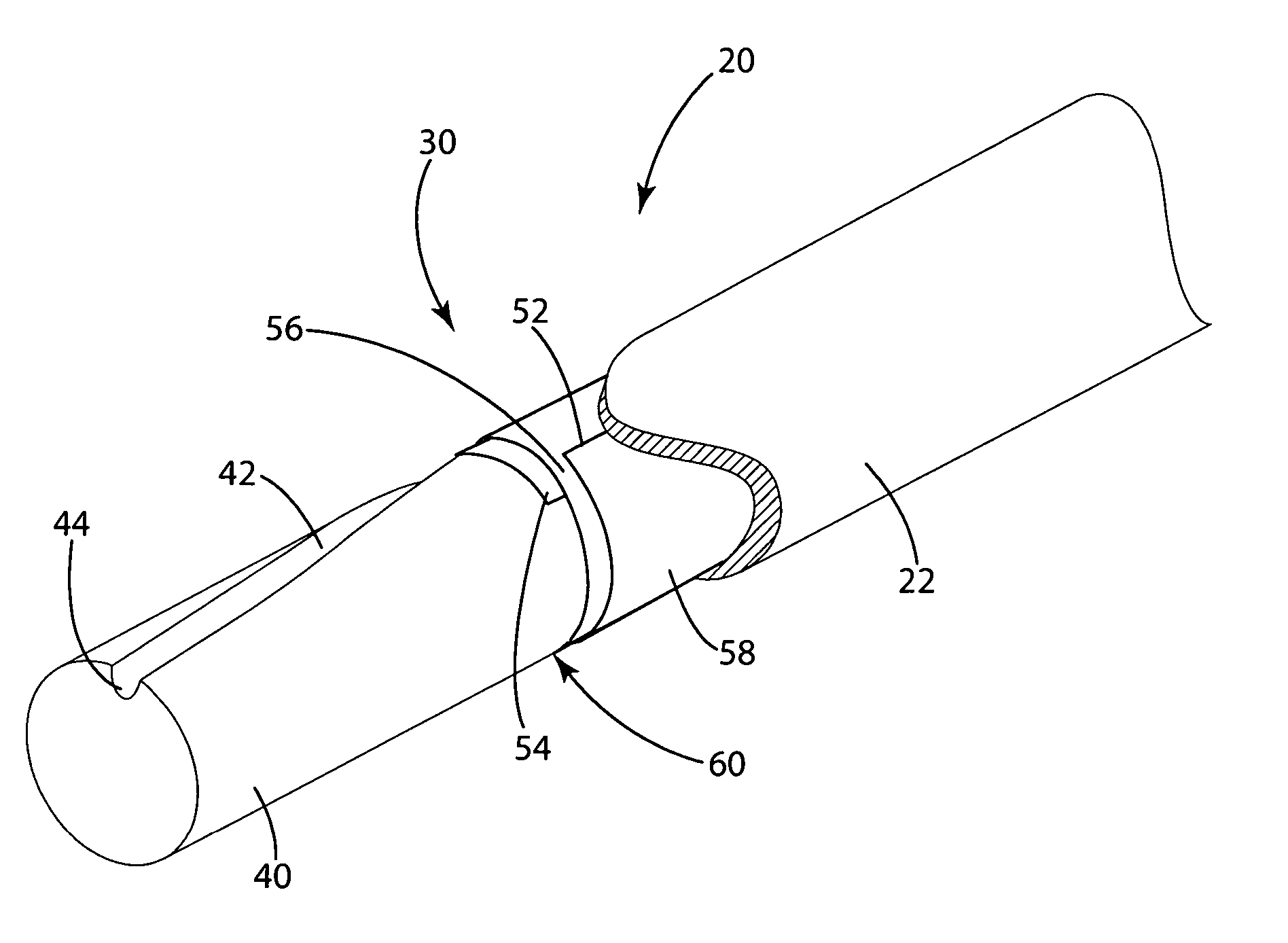
[0031]In a second embodiment, illustrated in FIGS. 5 and 6, the damper 30 is a dampening sheet 50, which acts as a multilayer energy dissipater. The dampening sheet 50 includes a first elongated end 52 coiled about a second elongated end 54 and an outer surface 58 and an inner surface 59. Preferably, the ends 52 and 54 are approximately parallel to axis 32. The first end 52 overlaps the second end 54 so that a boundary layer 55 is formed between the inner and outer surfaces. The first end 52 of the dampening sheets 50 generally overlaps the second end by at least 30°, but is coiled to overlap the second end less than 1470°. In the preferred embodiment, the first end is coiled at least one revolution about the second end so that an intermediate layer 56 is located between the first and second ends 52, 54 with a boundary layer between each of the first end and second end and the intermediate layer 56 (FIB. 5). Inventors have found that up to three full rotations provide the best absor...


PUM


Abstract

A lightweight damper for reducing noise and vibration in torque transferring assemblies that is easily assembled and cost efficient. The damper may be formed from a foam material having a density less than 1.4 lb / ft3, and includes an outer surface that is resiliently biased against the inner surface of a tubular shaft when installed. In a second embodiment, the damper is formed from a sheet of material that dissipates energy such as noises and vibrations through movement of the layers relative to each other. In third embodiment, the dampening sheet and foam damper are combined to provide a damper that dampens noises and vibrations across a large frequency range.

Description

BACKGROUND OF THE INVENTION[0001]The present invention relates to a damper for reducing noise, vibration, and harshness issues associated with torque transferring assemblies, such as vehicle driveshafts and propshafts.[0002]Torque transferring assemblies are widely used in vehicles to transfer torque between the engine and the wheels. Typically a torque transferring assembly is arranged between a transmission and an axle assembly, a power transfer unit and an axle assembly, or a transfer case and an axle assembly. To reduce weight, torque transferring assemblies typically include a tubular shaft spanning between a source of rotational energy and the axle assembly. Tubular shafts transmit and amplify vibration and noises from the engine, axle assembly, transmission, transfer case, and wheels. Yet another problem with tubular shafts in torque transferring assemblies is that they produce undesirable noise when rocks or other debris forcefully impact the tubular shaft during vehicle ope...

Claims


Application Information

Patent Timeline
Patent Type & Authority Patents(United States)
IPC IPC(8): F16C3/02F16D13/68
CPCF16F15/10F16C3/02Y10T464/50F16F1/37F16F2224/0225F16C3/023
Inventor HAILE, YOHANNES G.KAMRATH, THOMAS E.SCHENCK, RAND S.SZALONY, NORMAN
Owner AUTOMOTIVE COMPONENTS HOLDINGS
Why Eureka
Try Eureka