
Guide wire

a technology of guide wires and wires, applied in the field of guide wires, can solve the problems of limiting the diameter of the distal end portion of the core wire, affecting the safety of catheters, so as to achieve balanced rigidity and flexibility.

Inactive Publication Date: 2006-08-01
NIPRO CORP
View PDF16 Cites 11 Cited by
  • Summary
  • Abstract
  • Description
  • Claims
  • Application Information

AI Technical Summary

Benefits of technology

[0007]The present invention has been made in view of the above-mentioned circumstances, and provides a guide wire having a balanced rigidity and flexibility. This guide wire can be deformed at a distal end portion thereof, easily pass through a narrowed portion in a blood vessel, and can transmit a torque and a pushing force generated at a proximal end of the guide wire to a distal end thereof. Using the guide wire of the present invention, there is no fear that the distal end of the guide wire will puncture a blood vessel.
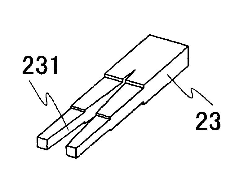
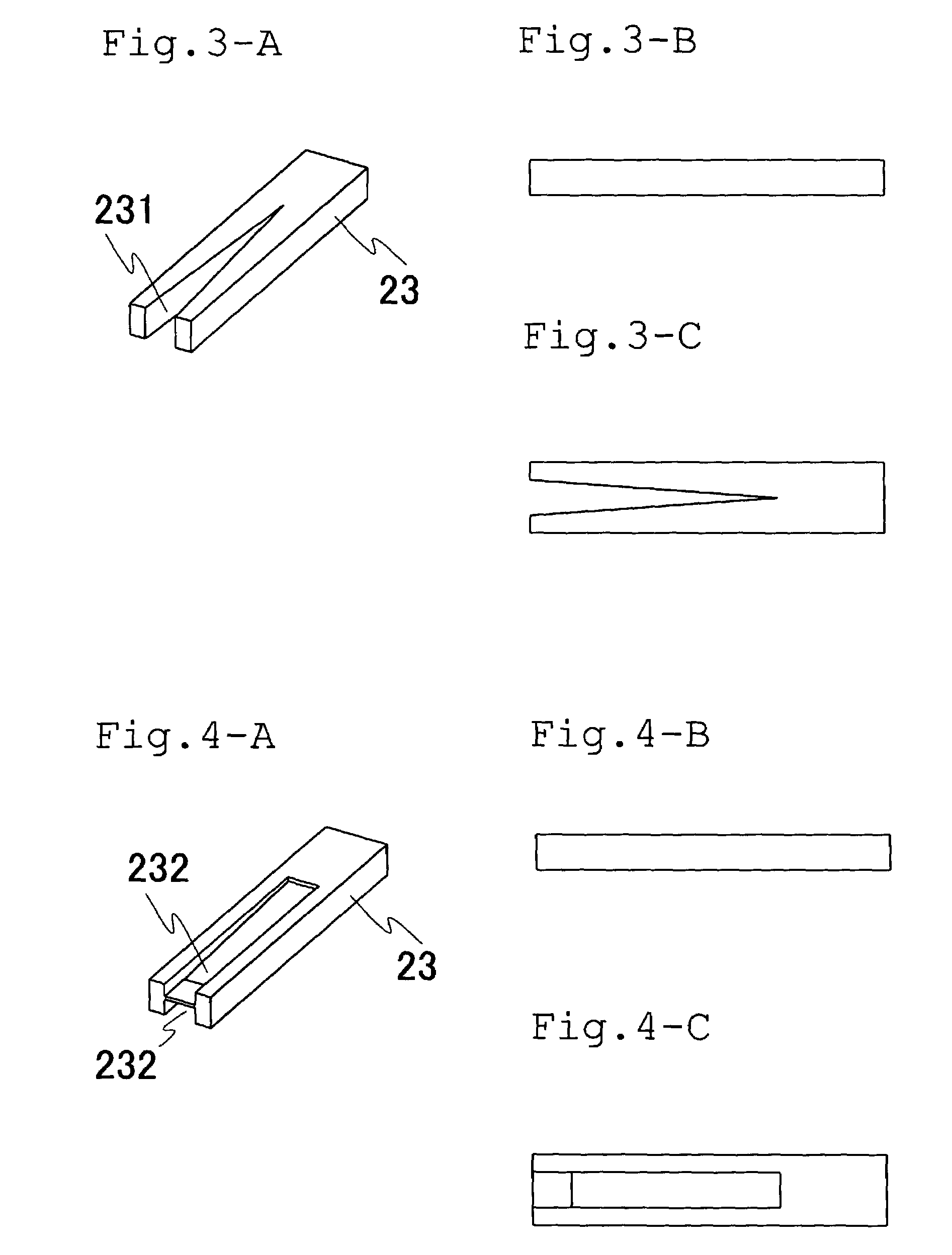
[0008]In order to solve the above-mentioned problem, the inventors of the present invention discovered that, when a core wire is formed so that the flexibility of a distal end portion of the core wire gradually increases toward a distal end thereof by providing a cutout section or a rased section in a tabular shaped portion, which has a constant width and is provided at a distal end of the core wire, a guide wire free from the above-mentioned drawbacks can be provided, and reached the present invention.

Problems solved by technology

It is very difficult to insert a catheter into an artery because the pressure in an artery is higher than that in a vein.
Therefore, there is a limit to the extent of reduction of the diameter of the distal end portion of the core wire.
Therefore, there is a fear that the distal end of the guide wire will puncture a blood vessel due to a pushing force transmitted from the proximal end of the guide wire.
When a material of the distal end portion of the core wire is changed to a material capable of giving flexibility to the guide wire, it is difficult for torque generated at the proximal end of the guide wire to be transmitted to the distal end thereof.

Method used


Image

  • Guide wire
  • Guide wire
  • Guide wire

Examples


Embodiment Construction

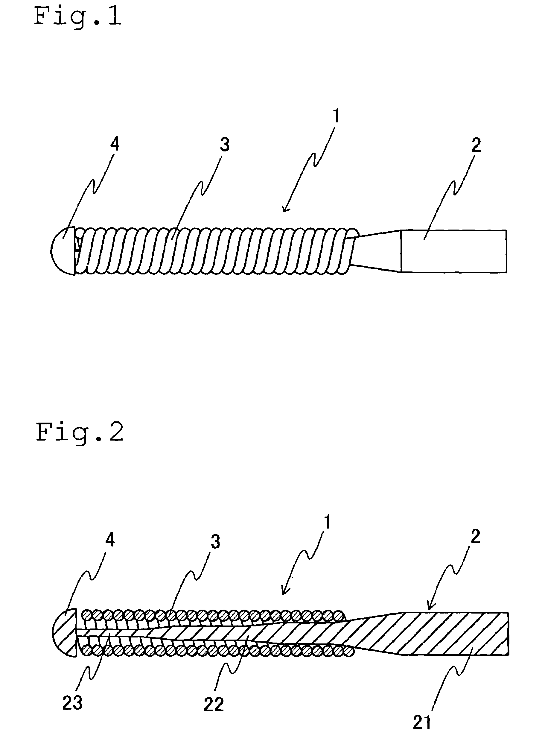
[0021]In the guide wire according to the present invention, a distal end indicates an end at which a patient is pierced (left side in FIGS. 1, 2 and 10), while a proximal end indicates an end which is held by medical personnel when the guide wire is operated, and which is at the opposite end of the distal end (right side in FIGS. 1, 2 and 10). An axial direction indicates a direction connecting the above-mentioned distal end and proximal end together, and a diametrical direction indicates a direction perpendicular to the axial direction.

[0022]As shown in FIG. 1, a guide wire 1 according to the present invention includes an elongated core wire 2, and a coil wire 3 provided on an outer circumference of a distal end of the core wire 2.

[0023]As shown in FIG. 2, the core wire 2 is preferably an elongated wire having a substantially circular diametrical cross section except at the distal end portion thereof. The core wire 2 includes, for example, a main portion 21 on the proximal end side...


PUM


Abstract

A guide wire having an elongated core wire provided with a tabular distal end portion, and a coiled wire provided on an outer circumference of the core wire, wherein the distal end portion of the core wire is provided with a cutout section or a rased section so that a diametrical cross-sectional area of the distal end portion of the core wire gradually decreases toward a distal end thereof.

Description

BACKGROUND OF THE INVENTION[0001]This invention relates to a guide wire used to introduce a catheter to a necessary position in a human body for a remedy or an examination.[0002]A catheter is used in medical treatment such as super selective angiography, percutaneous transluminal angioplasty (PTA), transcatheter arterial embolization (TAE) or percutaneous transluminal coronary angioplasty (PTCA), etc. In order to introduce the catheter into a human body, a guide wire has been heretofore used. The guide wire is a wire for guiding a catheter. The guide wire is mainly used in a percutaneous catheterization (Seldinger method). In this method, after a guide wire is inserted into a blood vessel, a catheter is inserted into a blood vessel with the guide wire used as a shaft. It is very difficult to insert a catheter into an artery because the pressure in an artery is higher than that in a vein. The catheter can be easily inserted into an artery by placing a guide wire in the artery in adva...

Claims


Application Information

Patent Timeline
Patent Type & Authority Patents(United States)
IPC IPC(8): A61B5/00A61M25/00A61M5/178A61M25/01A61M25/09
CPCA61M25/09A61M2025/09083
Inventor OSAWA, SHINJIINOUE, HIROYUKIFUKUCHI, KAZUHIROTANIMOTO, MASAHISA
Owner NIPRO CORP
Learn More