Switched filterbank and method of making the same

a filterbank and switch technology, applied in the field of switchbank and switch filterbank, can solve the problems of high cost associated with discrete filters, difficult to build distributed stripline filters into standard rf pwb stackups without grossly driving up costs

Active Publication Date: 2006-08-01
NORTHROP GRUMMAN SYST CORP
View PDF15 Cites 38 Cited by
  • Summary
  • Abstract
  • Description
  • Claims
  • Application Information

AI Technical Summary

Problems solved by technology

The cost associated with discrete filters is substantially high.
Distributed stripline filters are difficult to build into standard RF PWB stackups without grossly driving up costs.

Method used


Image

  • Switched filterbank and method of making the same
  • Switched filterbank and method of making the same
  • Switched filterbank and method of making the same

Examples


Embodiment Construction

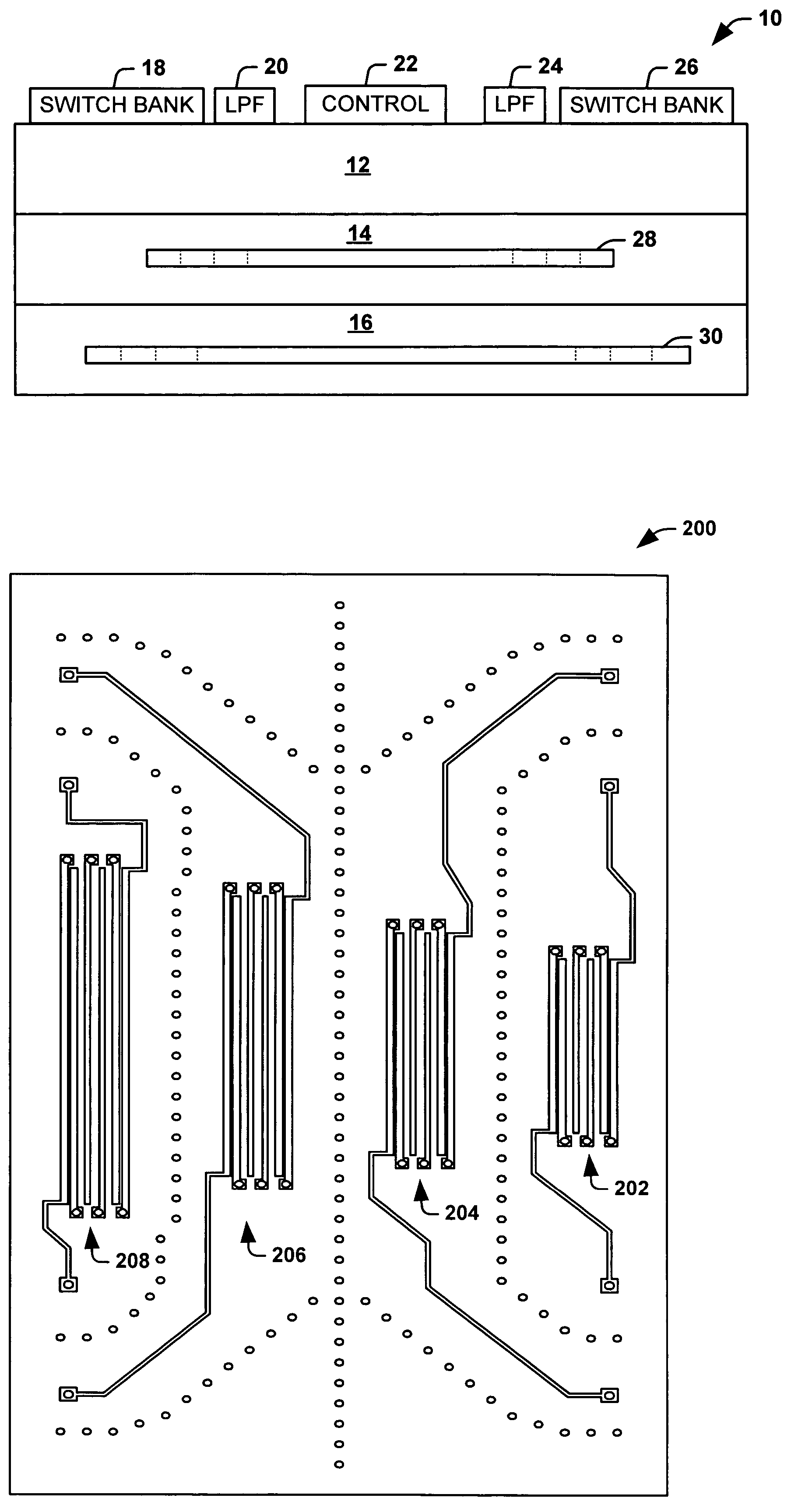
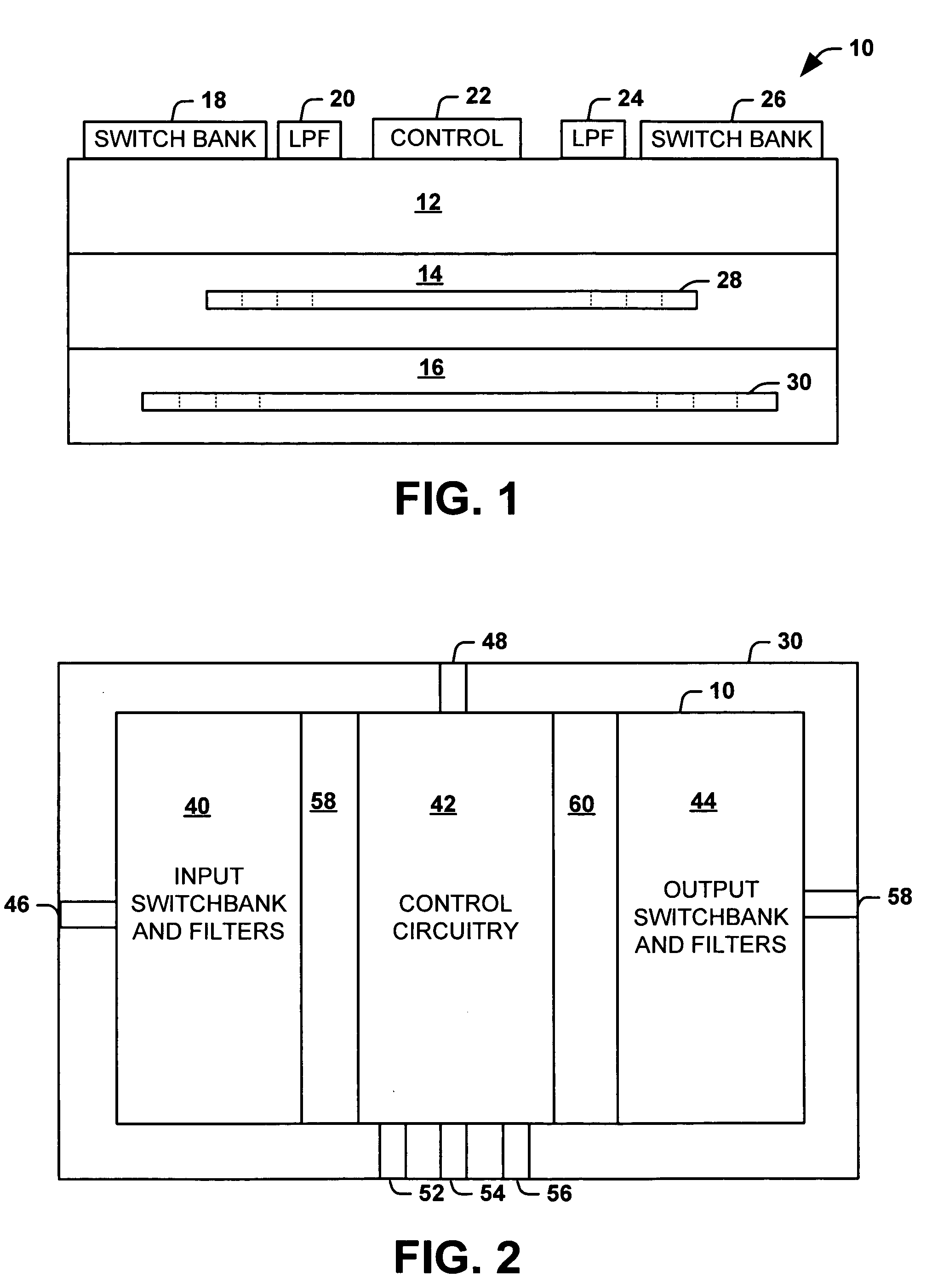
[0016]The present invention relates to a switched filterbank and method of making the same. The switched filterbank is comprised of a multi-layer circuit assembly. The multi-layer circuit assembly can comprise a radio frequency (RF) printed wiring board (PWB) assembly, a low temperature co-fired ceramic (LTCC) structure, a semiconductor structure or other stacked circuit assembly. The multi-layer circuit assembly includes an active subassembly with a plurality of stripline filter devices fabricated in one or more stripline subassemblies stacked below the active subassembly. The stripline filter devices are laid out side-by-side in one or more stripline subassemblies stacked below the active subassembly to maximize density and preserve performance. The stripline filter devices are suited for higher frequency bandwidths, such as bandwidths operating in the L-band region (e.g., 400 MHZ to about 2.4 GHZ).

[0017]FIG. 1 illustrates an integrated switched filterbank 10 in accordance with an...


PUM


Abstract

An integrated switched filterbank and method of forming an integrated switched filterbank is disclosed. One embodiment includes a switched filterbank that includes an active subassembly, a plurality of active devices mounted to the active subassembly, and a stripline filter subassembly stacked below the active subassembly. The stripline filter subassembly includes a plurality of stripline filters of varying passbands embedded therein, wherein the plurality of stripline filters are coupled to active devices mounted on the active subassembly through a set of contacts extending from the stripline filters through the active subassembly to at least one of the plurality of active devices.

Description

TECHNICAL FIELD[0001]The present invention relates generally to electronic devices, and more particularly to a switched filterbank and method of making the same.BACKGROUND OF THE INVENTION[0002]Switched filterbanks are typically used in transceivers for pre-selection or post-selection of signals or channels. Filterbanks are typically constructed with a bank of discrete filters with a switch matrix to select the filter of choice. Filters are typically sub-octave and used to enhance receiver (RX) selectivity by rejecting unwanted signals at image frequencies and other points of spurious sensitivity. On the transmitter (TX) side, filters are used to reject unwanted spurious and harmonics prior to final amplification through a power amp stage. Physical implementation of switched filterbanks typically involve a 1:N switchbank, a bank of N discrete filters, and a N:1 switchbank. A typical planar implementation has significant area allocated to the switchbanks and filters. Much area is all...

Claims


Application Information

Patent Timeline
Patent Type & Authority Patents(United States)
IPC IPC(8): H01P1/20H01P1/203
CPCH01P1/20336
Inventor GOYETTE, WILLIAM R.
Owner NORTHROP GRUMMAN SYST CORP
Why Eureka
Try Eureka