
Passive reflector for a mobile communication device

a mobile communication and reflector technology, applied in the structural form of radiating elements, electrical devices, antenna supports/mountings, etc., can solve the problems of further complicated design requirements and degraded transmission efficiency, and achieve the effect of improving both transmission and reception of signals

Inactive Publication Date: 2006-08-01
DE LA TORRE BARREIRO JOSE LUIS +1
View PDF8 Cites 12 Cited by
  • Summary
  • Abstract
  • Description
  • Claims
  • Application Information

AI Technical Summary

Benefits of technology

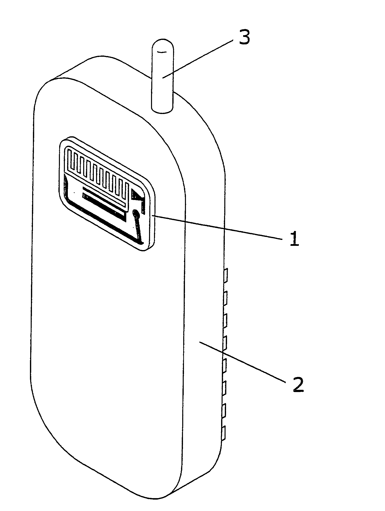
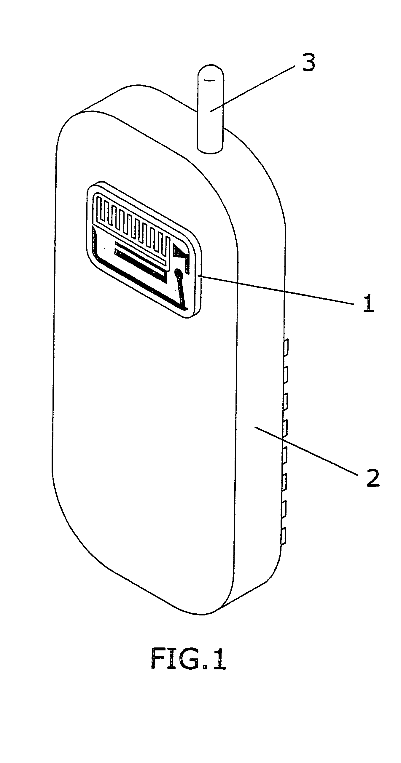
[0016]The invention of a passive signal-capturing reflector consists of a capturer with an exceptional gain in a large bandwidth, allowing multiroute communication or communication from vehicles in difficult situations or where coverage is poor: It provides a directional radiation beam towards the antenna of the portable telephone, allowing to concentrate as much radiation as possible and thereby increasing the gain.
[0017]This reflector allows improving the coverage, improving the gain, an easier operation of the set by the user as it can be pointed in any direction, and also allows reducing the radiation on the face adjoining the portable telephone and thus its incidence on the human body.
[0018]The reflector is disposed attached to the rear part of the portable telephone casing and does not require any additional installation. It provides a directional radiation beam on the antenna, increasing the total gain.
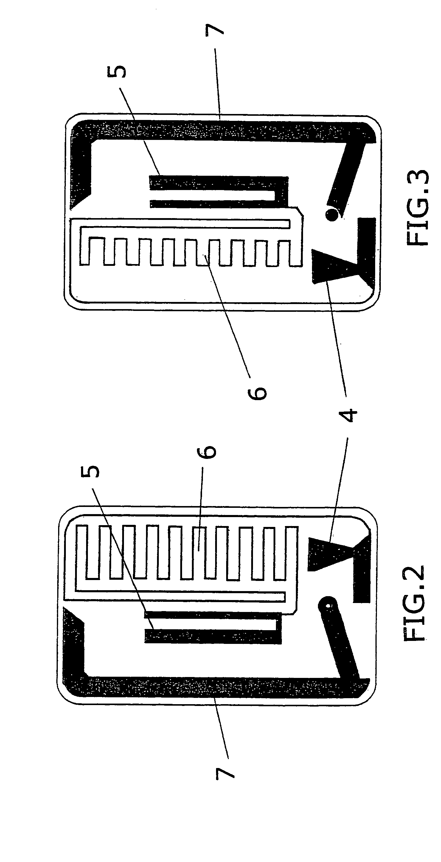
[0020]The design of said reflector allows adjusting its impedance and that of the telephone antenna, and comprises a careful track design with the accurate measurements of a percentage of the wavelength at the working frequency.
[0021]The distance between the reflector and the telephone wavelength is 0.15 λ. This distance between the elements is what gives the capturer an optimal gain, as otherwise the fields would interact with each other, reducing the gain.

Problems solved by technology

It is also the case that the efficiency of transmission degrades with the proximity of the human body, as the antenna is affected by the movements of the body.
These design requirements are further complicated by having to manufacture the sets as small as possible.

Method used


Image

  • Passive reflector for a mobile communication device
  • Passive reflector for a mobile communication device
  • Passive reflector for a mobile communication device

Examples


Embodiment Construction

[0016]The invention of a passive signal-capturing reflector consists of a capturer with an exceptional gain in a large bandwidth, allowing multiroute communication or communication from vehicles in difficult situations or where coverage is poor: It provides a directional radiation beam towards the antenna of the portable telephone, allowing to concentrate as much radiation as possible and thereby increasing the gain.

[0017]This reflector allows improving the coverage, improving the gain, an easier operation of the set by the user as it can be pointed in any direction, and also allows reducing the radiation on the face adjoining the portable telephone and thus its incidence on the human body.

[0018]The reflector is disposed attached to the rear part of the portable telephone casing and does not require any additional installation. It provides a directional radiation beam on the antenna, increasing the total gain.

[0019]Said reflector is constructed on a gold-plated fibreglass plate prot...


PUM


Abstract

Reflector that when associated to a portable telephone allows concentrating a maximum amount of radiation, providing a directional radiation source allowing an increased signal gain, greater coverage, reduced radiation on the face of the circuit attached to the telephone and a lower incidence on the human body. The reflector is attached on the casing on the portable telephone, constructed on a fiberglass plate and comprises two faces on which are arranged a number of tracks such that the radiation between the reflector and the portable telephone antenna is adjusted. The support is conformed by the reflector itself, to which are adhered two double strips, one for attachment to the telephone and another for attachment to an ornamental strip that is provided on its outer face with an attachment area and an available area.

Description

[0001]This application is a 371 of PCT / ES03 / 00478 filed on Sep. 24, 2003.OBJECT OF THE INVENTION[0002]The object of the present invention is a passive signal-capturing reflector that when installed on the casing of mobile telephones or the like improves both the transmission and reception of the signals, as well as the support on which this reflector can be incorporated, which is adhered to the mobile telephone.[0003]The present invention of a passive reflector is characterised in that when installed on a mobile telephone or the like it allows obtaining the greatest possible gain on the required bandwidth.[0004]The present invention is also characterised by allowing an exceptional gain on a large bandwidth, allowing communication from locations where signal limitations prevent a good coverage, or from moving vehicles in difficult conditions.[0005]Also the object of the present invention is the support on which the passive reflector comprised of a number of adhesive layers and attach...

Claims


Application Information

Patent Timeline
Patent Type & Authority Patents(United States)
IPC IPC(8): H01Q1/24H01Q1/38
CPCH01Q1/245H01Q1/38H01Q1/248
Inventor DE LA TORRE BARREIRO, JOSE LUISESTEBAN AZPIROZ, FRANCISCO LORENZO
Owner DE LA TORRE BARREIRO JOSE LUIS
Learn More