Portable terminal with rotatable axial flip unit and dual lens arrangement

a technology of axial flip unit and portable terminal, which is applied in the field of portable terminal, can solve the problems of inability to realize a portable terminal capable of combining all the above-mentioned functions, too complicated circuitry and structure of a device, and too deteriorated operational performance to solve faults

Inactive Publication Date: 2006-08-01
LENOVO INNOVATIONS LTD HONG KONG
View PDF9 Cites 79 Cited by
  • Summary
  • Abstract
  • Description
  • Claims
  • Application Information

AI Technical Summary

Benefits of technology

[0022]In order to solve the above conventional problems, a second object of the present invention is to provide a portable terminal provided with a function of a portable TV telephone capable of easily sending an image such as a scene nearby seen from the side of a user, to a communication party.

Problems solved by technology

First, though there are a lot of advantages in adopting the method of providing one portable terminal with a plurality of functions such as a telephone, a TV telephone, a digital camera, a digital video camera, a pen input terminal and the like, the conventional portable terminal can combine only two or three functions. Especially, it is impossible to realize a portable terminal capable of combining all the above-mentioned functions.
This is because if a plurality of functions are provided within one small and light portable terminal, the circuitry and structure of a device becomes too complicated and the operational performance is too deteriorated to solve faults.
Second, though a use of sending various images such as scenes and substances from a visiting place is required as a function of a portable TV telephone, making good use of the portability of the portable terminal, a portable TV telephone by the conventional portable terminal is very inconvenient for picking up an image other than a user's own face.
If the direction is changed, a user cannot see the display on the liquid crystal monitor.
The conventional portable terminal, however, can operate only in a way of opening and closing the flip unit and the main unit, and it cannot be adjusted in the other directions flexibly.

Method used


Image

  • Portable terminal with rotatable axial flip unit and dual lens arrangement
  • Portable terminal with rotatable axial flip unit and dual lens arrangement
  • Portable terminal with rotatable axial flip unit and dual lens arrangement

Examples


first embodiment

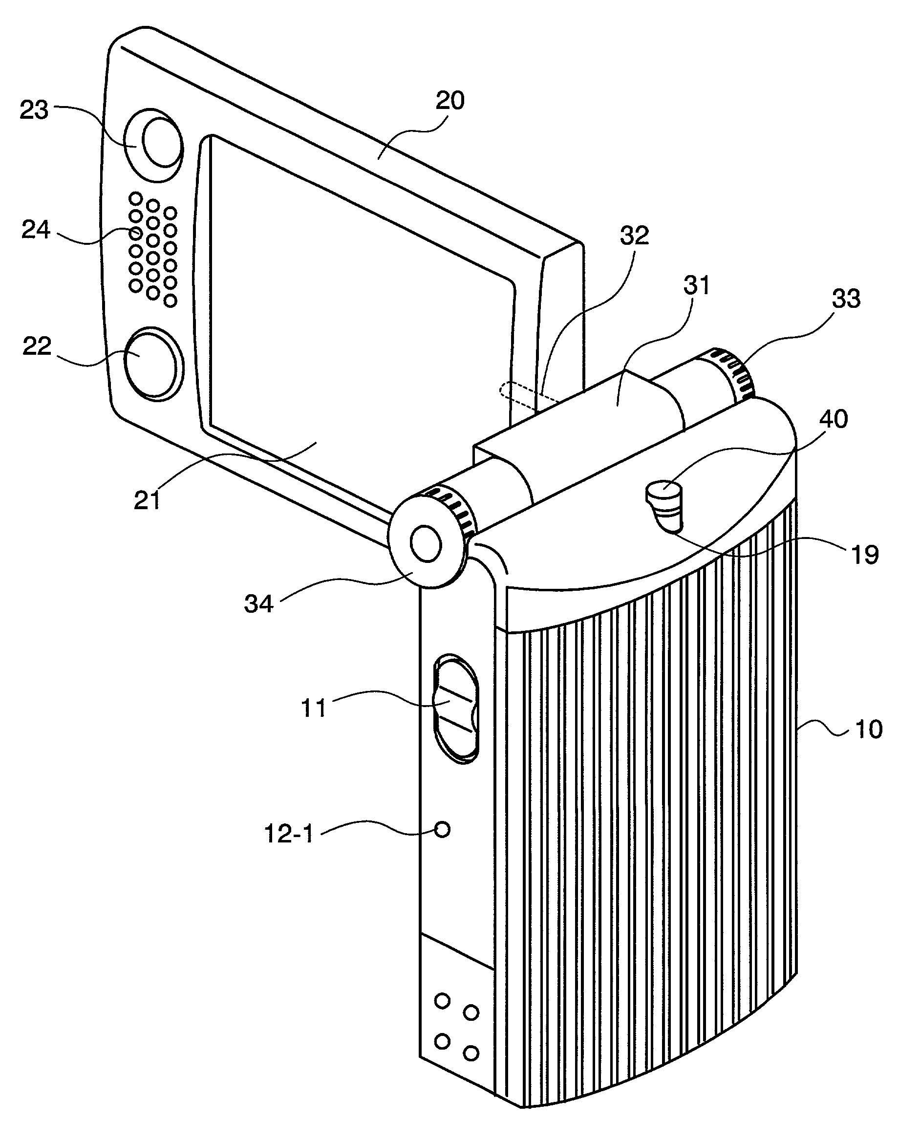
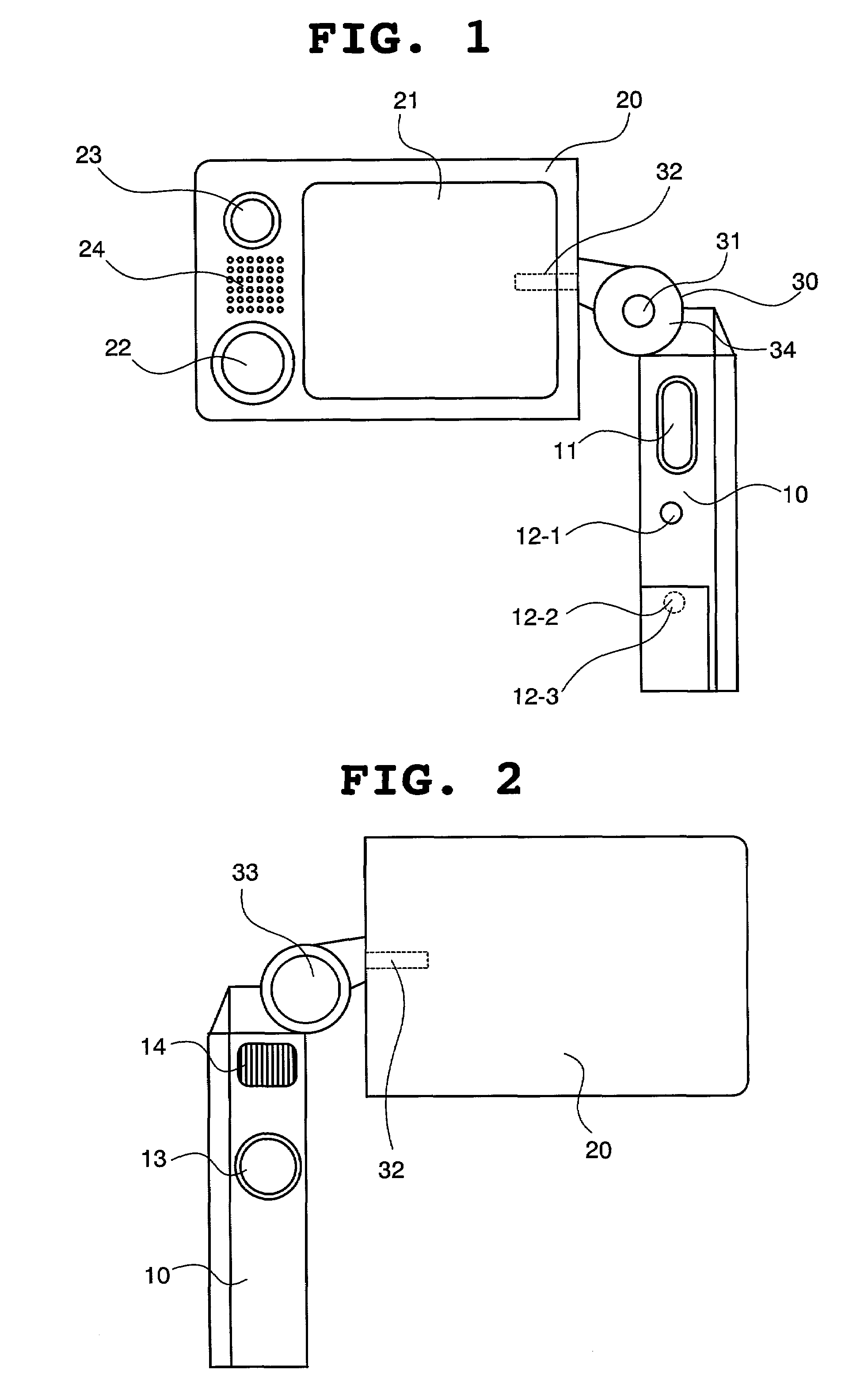
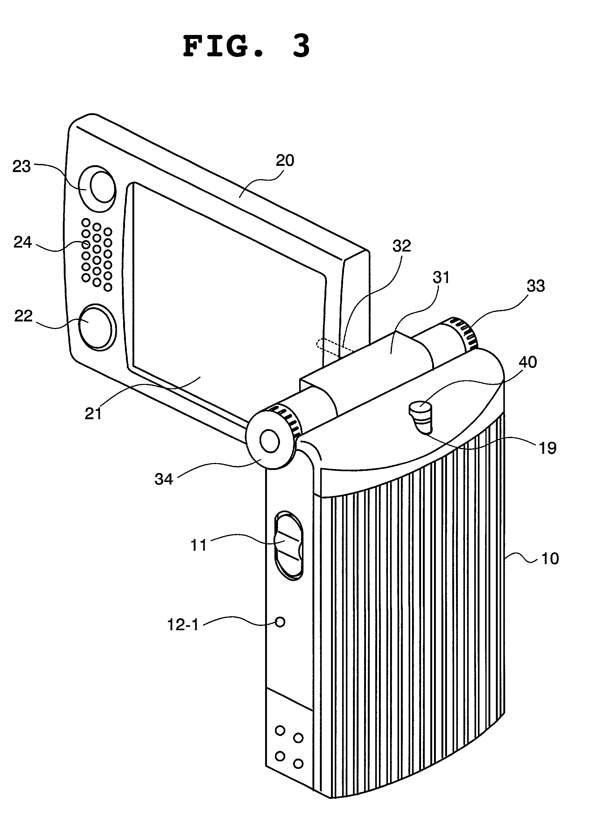
[0201]FIGS. 1 to 12 are views each showing a main unit and a flip unit of a portable terminal according to the present invention, which are put in various directions and seen from various directions.

[0202]With reference to FIGS. 1 to 12, in the portable terminal of the embodiment of the present invention, a main unit 10 and a flip unit 20 are connected in a movable way through an axial unit 30.

[0203]The axial unit 30 is provided with an opening / shutting axis 31 and a rotation axis 32 as illustrated in FIG. 1. The opening / shutting axis 31 is connected to the portable terminal so that the main unit and the flip unit can be relatively rotatable, and the rotation axis 32 is connected there in a rotatable way in the vertical direction across the rotation of the opening / shutting axis 31.

[0204]Further, a first photographic lens 33 for a digital camera is provided on one end of the opening / shutting axis 31 and an operation dial 34 is provided on the other end thereof.

[0205]The flip unit 20 ...

second embodiment

[0238]This time, a portable terminal according to the present invention will be described.

[0239]In the second embodiment, activation of various functions provided in the portable terminal of the present invention is controlled depending on the relative direction of the main unit 10 and the flip unit 20.

[0240]When the relative direction of the main unit 10 and the flip unit 20 suitable for each function described in the first embodiment is detected by the axial unit state sensor 55, the corresponding function is activated or it is ready for activation.

[0241]FIG. 14 is a flow chart for use in describing the control of the portable terminal of this embodiment.

[0242]With reference to FIG. 14, the axial unit state sensor 55 detects the respective angles of the opening / shutting axis 31 and the rotation axis 32 of the axial unit 30 in order to recognize the relative direction of the main unit 10 and the flip unit 20 (Step 1401).

[0243]When the opening / shutting axis 31 is closed (Step 1402) ...

third embodiment

[0250]A portable terminal of the present invention will be described.

[0251]The portable terminal of the third embodiment of the present invention is different from the first embodiment and the second embodiment in that a second speaker 25 is provided on the opposite side of the speaker phone 24 in the flip unit 20 as illustrated in FIGS. 15 and 16. Accordingly, in the case of using it as a portable telephone, it can be used with the outside of the flip unit facing to the inside of the main unit, by turning the flip unit 20 around the rotation axis 32 at 180°. In this case, a user's cheek doesn't come into contact with the touch panel monitor 21 when using it as the ordinal portable telephone, thereby enabling conversation without dirtying the surface of the monitor.

[0252]A combination of the second embodiment and the third embodiment is enabled by replacing Step 1406 with the phrase “the angle of the opening / shutting axis is in the range of 90° to 180° and the rotation axis is inver...


PUM


Abstract

This portable terminal comprises a main unit having a microphone, a key operation unit, and a radio sending / receiving function of image and sound, a rotation axial unit having a video camera and an operation dial, an image display unit with a touch panel capable of displaying an image taken by the video camera, a received image and a screen for input operation, and a flip unit having the image display unit, a CCD camera, a speaker and an operation button. The rotation axial unit further includes an opening / shutting axis for connecting the main unit and the flip unit in a mutually rotatable way and a rotation axis for connecting the flip unit in a way of rotating the flip unit across the above rotation in the horizontal direction, and when the flip unit is opened and rotated across, it is used as a video camera with a monitor.

Description

BACKGROUND OF THE INVENTION[0001]1. Field of the Invention[0002]The present invention relates to a portable terminal, and more particularly to a small-sized portable terminal for compactly realizing various functions of a telephone, a TV telephone, a digital camera, a digital video camera, a pen input terminal and the like.[0003]2. Description of the Related Art[0004]A portable terminal is a small-sized device having a processing function of communication, image and information, convenient to carry and excellent in portability.[0005]As the conventional portable terminal widely used in the public, there are communication terminals and information terminals of, for example, a portable telephone, a PHS, a TV telephone, a digital camera, a digital video camera, and a pen input system.[0006]Recently, a portable terminal provided with some of these functions has made an appearance. In this method, since some functions are provided in one device, it is not necessary to carry several kinds ...

Claims


Application Information

Patent Timeline
Patent Type & Authority Patents(United States)
IPC IPC(8): H04N5/222G06F1/16G06F15/02H04B1/38H04B1/3822H04M1/00H04M1/02H04M1/21H04N5/225H04N7/14H04W28/00H04W88/02
CPCH04M1/021H04M1/0243H04M1/0245H04N5/2251H04N5/2258H04M1/0218H04N2007/145H04M2250/52H04M2250/22H04N23/531H04N23/45H04N23/631
Inventor SHIBATA, JUNICHIROYAMAGUCHI, SHUUJI
Owner LENOVO INNOVATIONS LTD HONG KONG
Why Eureka
Try Eureka