Magnetic pole insensitive switch circuit

a technology of insensitive switch and magnetic pole, applied in the field of switches, can solve problems such as the inability of the magnetic on-board switch to operate correctly

Inactive Publication Date: 2006-08-01
ALLEGRO MICROSYSTEMS INC
View PDF24 Cites 66 Cited by
  • Summary
  • Abstract
  • Description
  • Claims
  • Application Information

AI Technical Summary

Benefits of technology

[0014]In accordance with a further aspect of the present invention, a switch includes a Hall element and a threshold detector circuit having a substantially similar switching point for positive and negative magnetic fields. With this particular arrangement, a switch which utilizes a Hall effect device can operate correctly regardless of the orientation of the magnetic poles with respect to the Hall device. In one embodiment, the threshold circuit is provided as a comparator circuit.

Problems solved by technology

One problem with using a semiconductor switch in place of the Reed switch, however is that semiconductor devices, which include elements such as a Hall element, must be aligned in a particular manner with respect to the north and south poles of the magnet.
If the magnet and Hall element are not properly oriented (i.e. the appropriate ends of the hall element are not aligned with the appropriate magnetic poles) then the semiconductor switch will not operate correctly.
This leads to difficulties when it becomes necessary to replace the magnet or the semiconductor switch.

Method used


Image

  • Magnetic pole insensitive switch circuit
  • Magnetic pole insensitive switch circuit
  • Magnetic pole insensitive switch circuit

Examples


Embodiment Construction

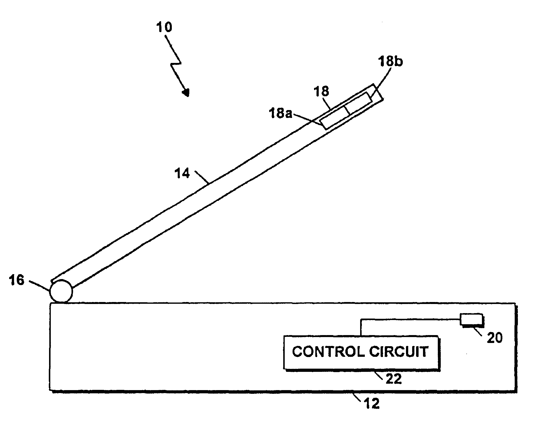
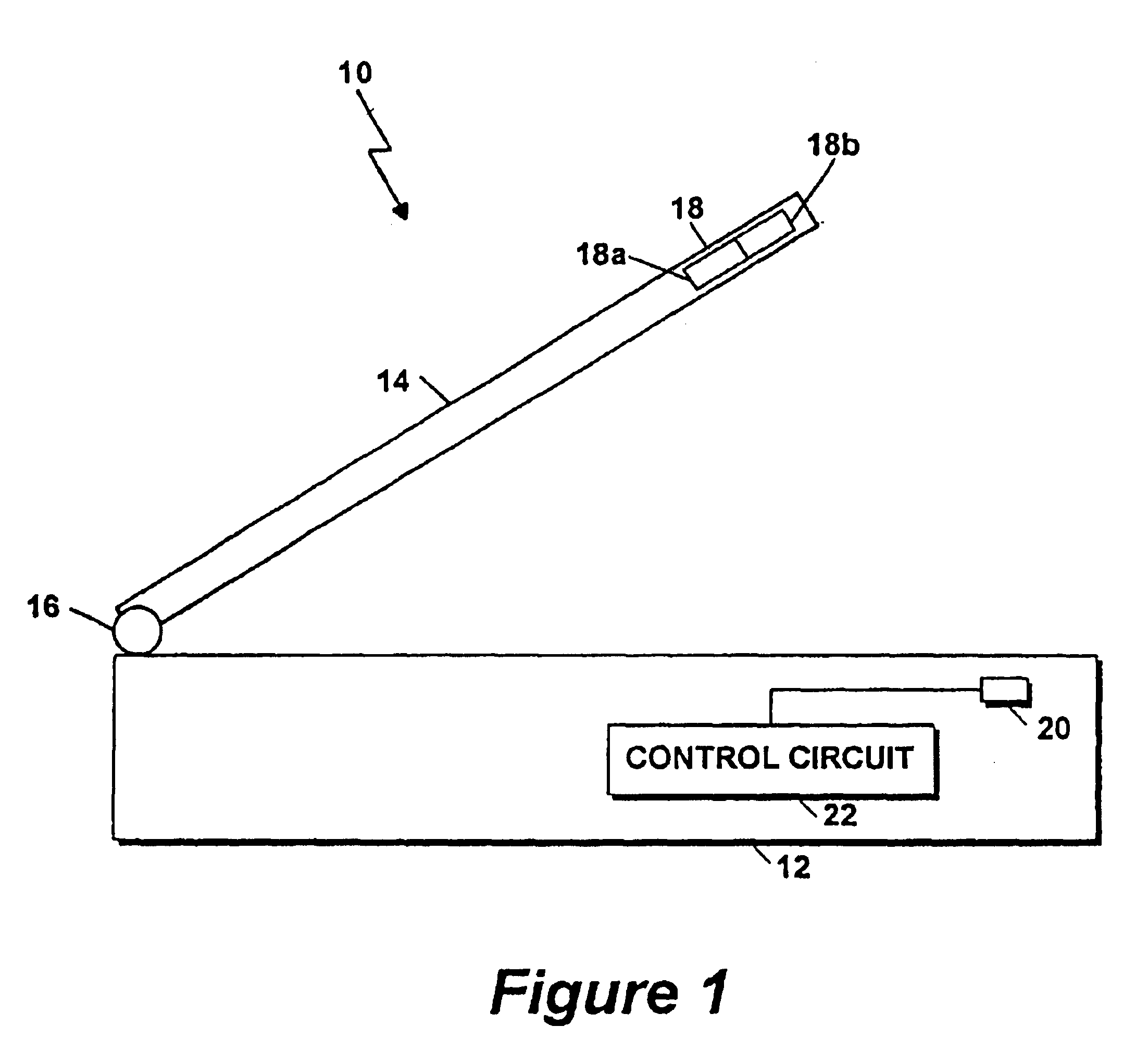
[0023]The following description sets forth an exemplary embodiment in which the present invention may be used. Specifically, certain reference is made below to a cellular telephone (cell phone) application. It should be understood, however, that the present invention finds use in a wide variety of applications and devices and is not limited to the exemplary embodiment described below. For example, the invention may be used in any device or apparatus which uses a magnetic device in conjunction with a movable portion such as a movable cover or door including cellular and non-cellular telephones, notebook or laptop computers and refrigerators.

[0024]Referring now to FIG. 1, a cellular telephone (cell phone) 10 includes a base portion 12 having a first end of a cover 14 movably coupled thereto. In this particular example, the first end of the cover 14 is movably coupled to the base 12 through a rotatable joint 16. Those of ordinary skill in the art will recognize of course that any coupl...


PUM


Abstract

A switch which is magnetic pole insensitive is described. The switch includes a Hall effect sensor coupled to a threshold circuit which provides an output signal indicative of the proximity of a magnet, and hence a magnetic field, to the Hall effect sensor regardless of the orientation of the magnet to the Hall effect sensor.

Description

CROSS REFERENCE TO RELATED APPLICATIONS[0001]This application is a continuation of U.S. patent application Ser. No. 09 / 997,148, entitled MAGNETIC POLE INSENSITIVE SWITCH CIRCUIT, filed on Nov. 27, 2001 now U.S. Pat. No. 6,622,012 which is a continuation of U.S. patent application Ser. No. 09 / 338,668, entitled MAGNETIC POLE INSENSITIVE SWITCH CIRCUIT, filed on Jun. 22, 1999 now U.S. Pat. No. 6,356,741 which is a continuation-in-part application of U.S. patent application Ser. No. 09 / 156,939, entitled MAGNETIC POLE INSENSITIVE SWITCH CIRCUIT, filed on Sep. 18, 1998 now abandoned.STATEMENT REGARDING FEDERALLY SPONSORED RESEARCH[0002]Not Applicable.FIELD OF THE INVENTION[0003]The present invention relates to switches and more particularly to switches which are responsive to magnet fields.BACKGROUND OF THE INVENTION[0004]As is known in the art, there exists a relatively large number of commercially available devices having a base or stationary portion and a movable cover or door portion ...

Claims


Application Information

Patent Timeline
Patent Type & Authority Patents(United States)
IPC IPC(8): H01H47/00H01H36/00H03K17/90H03K17/945H03K17/95H03K17/97H04B1/40H04M1/00H04M1/02
CPCH03K17/97H03K17/9517H01H1/54
Inventor BILOTTI, ALBERTOFORREST, GLENN A.VIG, RAVI
Owner ALLEGRO MICROSYSTEMS INC
Why Eureka
Try Eureka