

Electro-acoustic transducer and electronic device
- Summary
- Abstract
- Description
- Claims
- Application Information
AI Technical Summary
Benefits of technology
Problems solved by technology
Method used
Image

Examples
embodiment 1
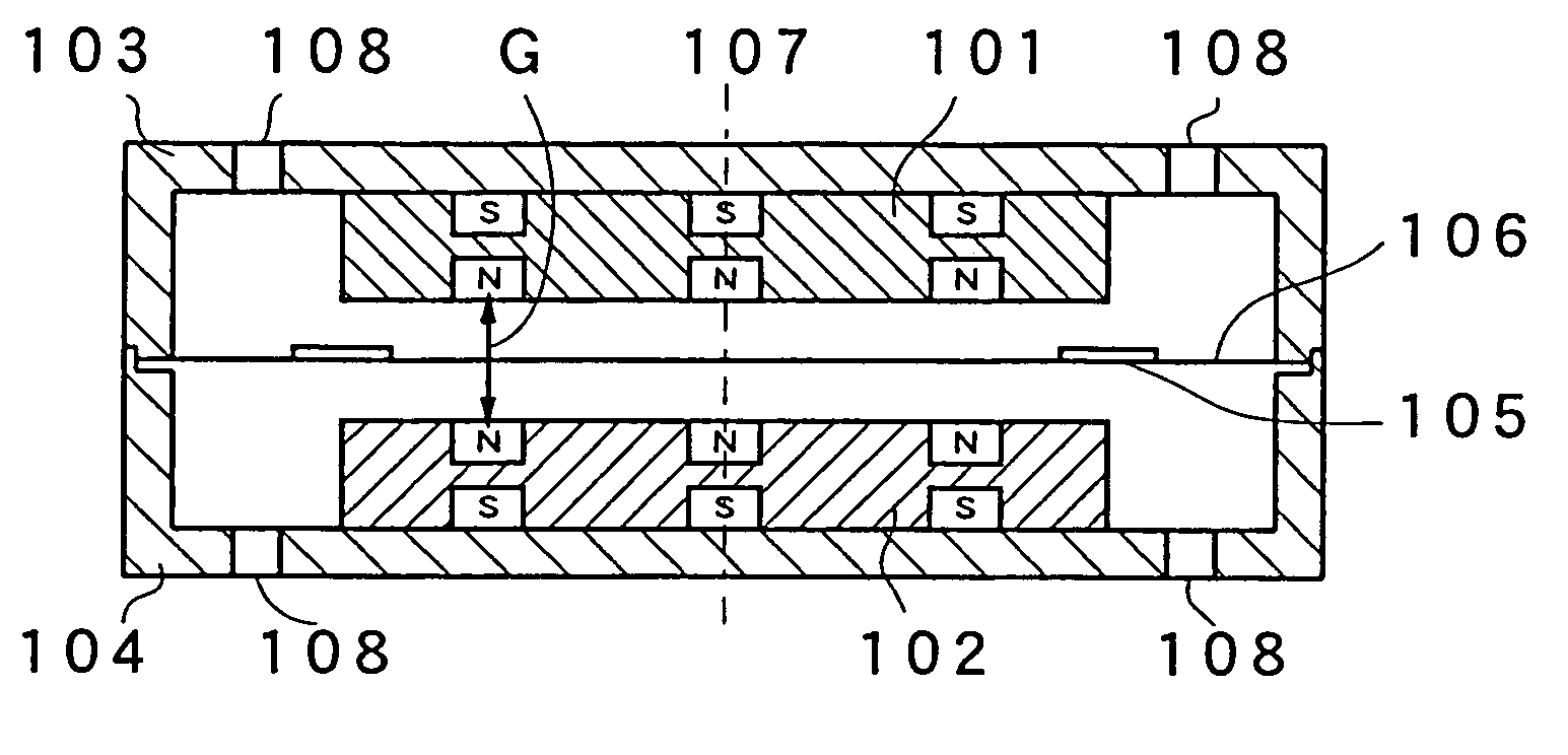
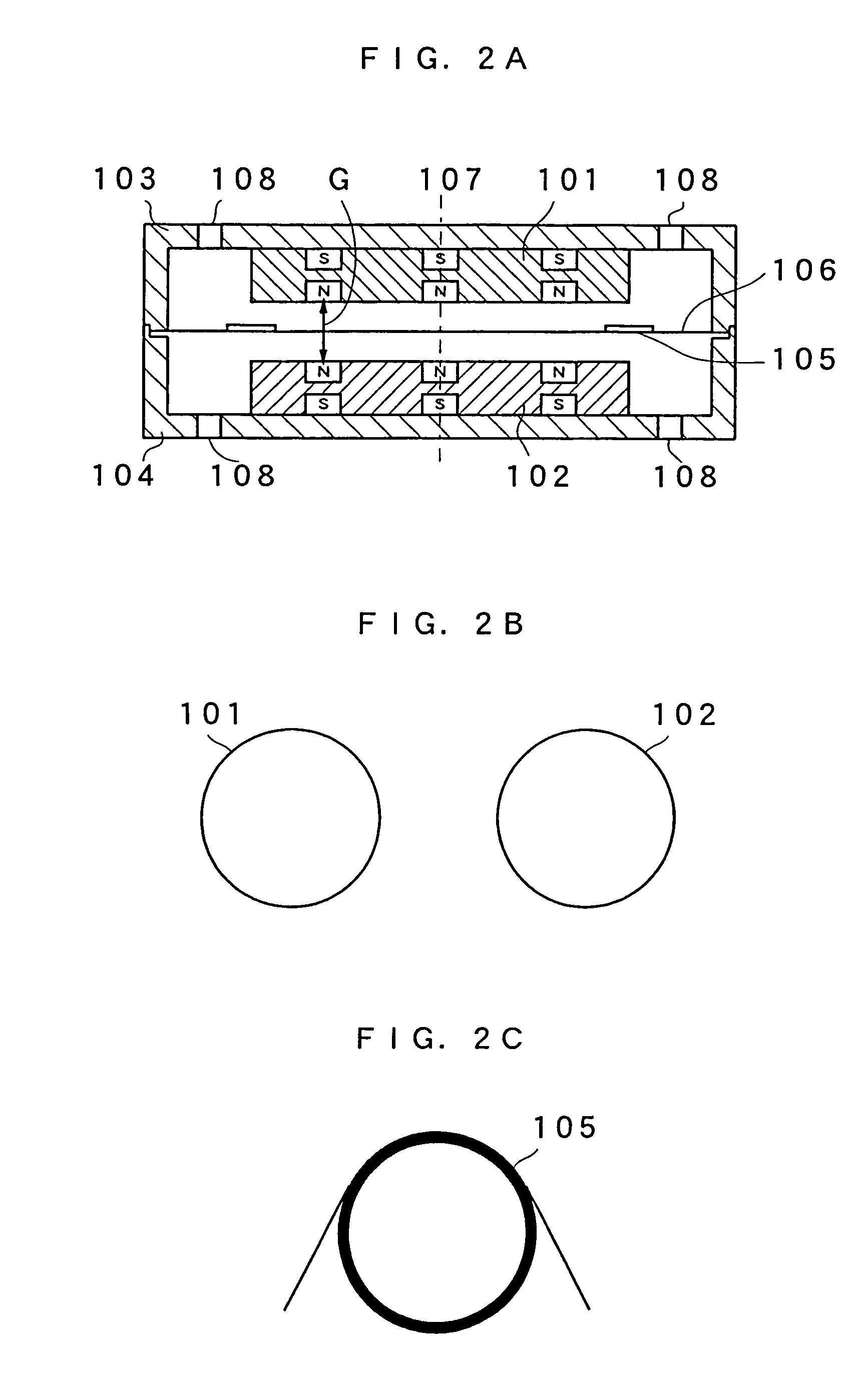
[0047]An electro-acoustic transducer of Embodiment 1 of the present invention will be described with reference to FIGS. 2 to 7. FIG. 2A is a cross sectional view of the electro-acoustic transducer, FIG. 2B is a plan view of first and second magnets, and FIG. 2C is a plan view of a drive coil. FIG. 3 is an assembly configuration view of this electro-acoustic transducer, and FIG. 4 illustrates magnetic flux vectors generating due to the first and second magnets. FIG. 5 is a graph showing the relationship between the distance from a center axis 107 in the center portion of a gap G in the radius direction and the magnetic flux density. FIG. 6 is a graph showing the relationship between the distance from the center portion of the gap G in the direction of vibration at the position of the drive coil and the magnetic flux density.
[0048]The electro-acoustic transducer of the present embodiment is formed as follows. A first magnet 101 and a second magnet 102, respectively, are held within an...
embodiment 2
[0063]FIG. 8 is a cross sectional view of an electro-acoustic transducer according to Embodiment 2 of the present invention, and FIG. 9 illustrates magnetic flux vectors generated by the first and second magnets. The electro-acoustic transducer of Embodiment 2 is formed as follows. An upper case 103 and a lower case 104 are the same as in Embodiment 1 and are integrated to form a housing. A first magnet 201 and a second magnet 202, respectively, are attached to the upper case 103 and the lower case 104. The first and second magnets 201 and 202 are of cylindrical forms and are secured to the upper case 103 and the lower case 104 so that the respective centers thereof coincide with the center axis 203. In addition, a drive coil 204 is adhered on a diaphragm 205 so as to be concentric with the diaphragm 205 relative to the center axis 203. Furthermore, the periphery of the diaphragm 205 is placed between the upper case 103 and the lower case 104 so as to be secured in the same manner a...
embodiment 3
[0074]FIG. 11 is a cross sectional view of an electro-acoustic transducer according to Embodiment 3 of the present invention, and FIG. 12 is a perspective view thereof. The electro-acoustic transducer of the present embodiment is formed as follows. First and second yokes 303 and 304 are provided around first and second magnets 301 and 302. The first and second yokes 303 and 304 are made of a magnetic material such as iron. Then, the first and second yokes 303, 304, the upper case 305 and the lower case 306, in frame forms, form a housing. In addition, a diaphragm 308 having a drive coil 307 is held in the center portion of the housing so that the diaphragm can freely vibrate. An edge 309 in an arc form is provided in the outer periphery portion of the diaphragm 308. The first and second magnets 301 and 302 are of cylindrical forms and are made of neodymium magnets, of which the energy product is, for example, 44 MGOe. Furthermore, the directions of magnetization are opposite to each...
PUM
 Abstract
Description
Claims
Application Information