
State detecting system and device employing the same

a state detection and state detection technology, applied in the direction of driving interaction, speed/acceleration/shock measurement device testing/calibration, etc., can solve the problems of significant time and attention required to obtain initial characteristics and a plurality, and it is difficult to accurately detect soc with respect to secular change and variation of environment, and achieves low cost and low cost. , the effect of simple calculation

Inactive Publication Date: 2006-08-01
HITACHI AUTOMOTIVE SYST LTD
View PDF9 Cites 26 Cited by
  • Summary
  • Abstract
  • Description
  • Claims
  • Application Information

AI Technical Summary

Benefits of technology

The present invention provides a state detection system for a power storage device that can accurately detect the state of the device by using measured information and pre-calculated correction information. The system includes a measuring means for measuring various parameters such as voltage, current, temperature, and electrolyte concentration, an arithmetic means for calculating the state of the device based on the measured information and pre-calculated correction information, and a communication means for communicating the calculated state to other devices. The system can detect the state of the device with high accuracy using a small amount of characteristic data and a simple calculation method. The correction means of the system can determine the correction value based on the discrepancy between the calculated result and the set information, or the difference between the calculated result and the set information. The system can be used in a power source unit, a power storage device, and an electric vehicle.

Problems solved by technology

However, many power storage means varies the full capacities depending upon SOH, temperature and so forth, it is difficult to accurately detect SOC with respect to secular change and variation of environment.
Therefore, significant time and attention have to be paid for obtaining the initial characteristics and a plurality of parameters of the power storage means.
However, no matter how complicated it is, the result of arithmetic operation is nothing but prediction on the basis of the theory or model of the battery characteristics.
Since it is not possible to directly measure the state of the battery, such as SOC or SCH, an important problem is how to derive the true value or logic.

Method used


Image

  • State detecting system and device employing the same
  • State detecting system and device employing the same
  • State detecting system and device employing the same

Examples


first embodiment

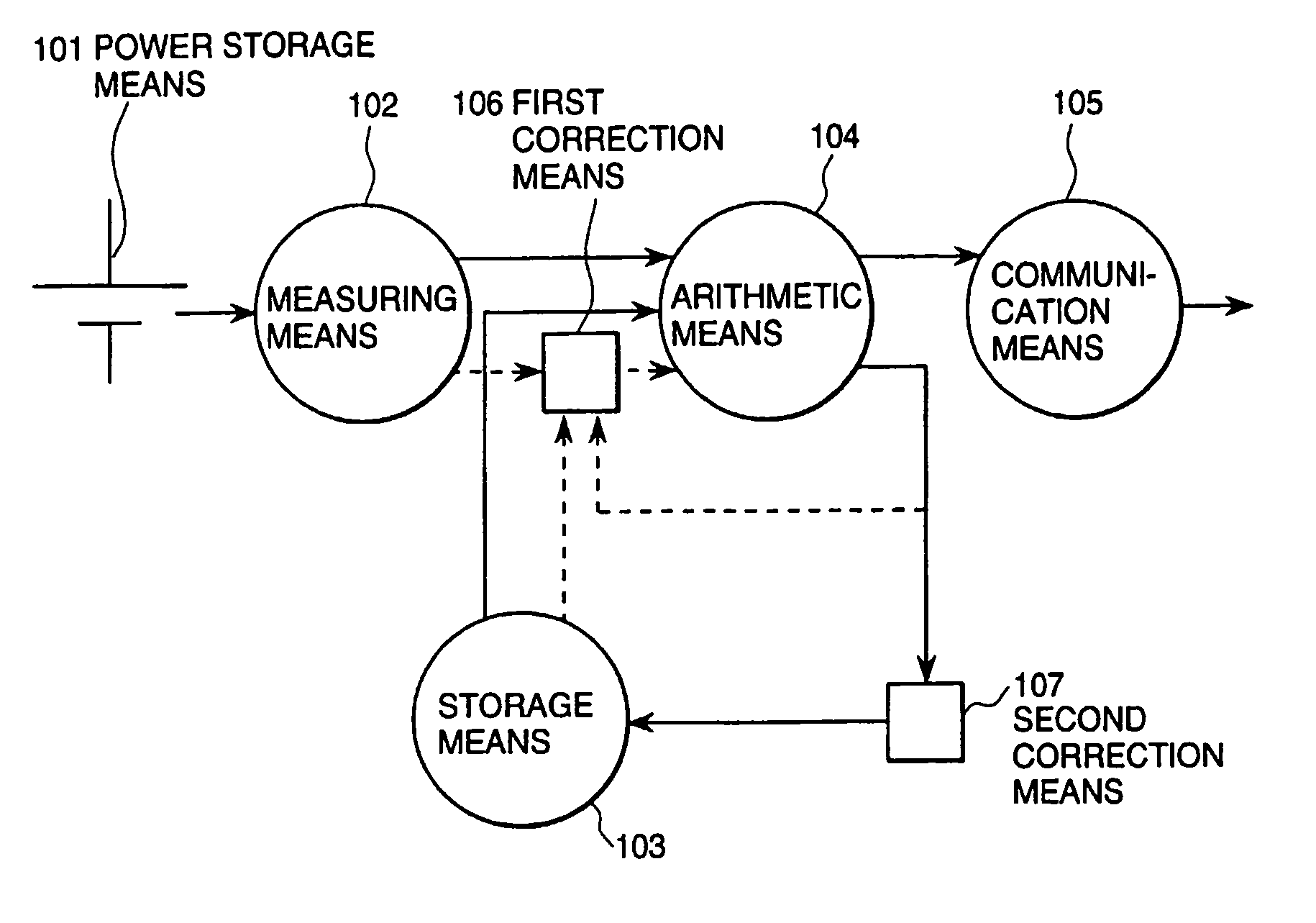
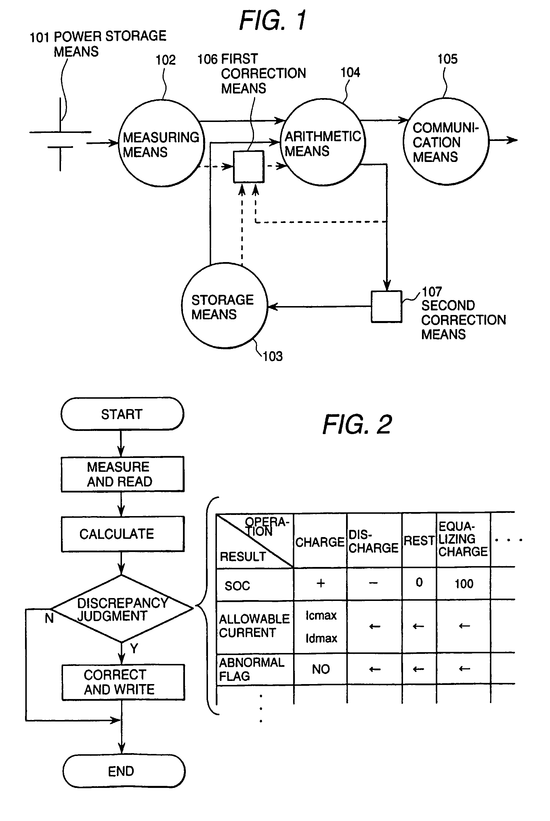
[0040]FIG. 1 is a constructional illustration of a power source unit according to the present invention. In FIG. 1, the reference numeral 101 denotes power storage means, 102 denotes measuring means, 103 denotes storage means, 104 denotes arithmetic means, 105 denotes communication means, 106 denotes first correction means and 107 denotes second correction means. The power storage means 101 is formed with a device having a power storage function, such as a lithium secondary battery, a nickel hydride battery, a lead seal battery, an electric double layer capacitor and so forth.

[0041]The measuring means 102 is formed with a sensor or an electric circuit measuring voltage, current, temperature, resistance, battery electrolyte concentration and so forth, to obtain necessary measured information.

[0042]The storage means 103 is constructed with a memory device, such as an EEPROM, flash memory, a magnetic disk and so forth to store calculation information including at least one of character...

second embodiment

[0049]FIG. 2 is a block diagram showing a state detection method of the power storage means according to the present invention. In FIG. 2, in a step of measuring and reading, voltage, current, temperature, resistance, electrolyte concentration and so forth of the power storage means 101 is measured to read the measuring value of the first correction means 106 or the arithmetic means 104 or a value of the storage means 103. In calculation, state of the power storage means 101 is calculated on the basis of the read value. In discrepancy judgment, the result of calculation and the set value or logic is compared to make judgment of discrepancy. If no discrepancy is found, process does end to repeat the same sequence. If discrepancy is found, related parameters are corrected at a step of correction and writing to terminate writing in the memory. By repeating this sequence, correction to feed back the discrepancy to subsequent arithmetic operation with learning can be performed.

[0050]Here...

third embodiment

[0062]The table 1 is a table showing a relationship between variation of SOC of the present invention and correction amount of Vp. With taking a time scale as t, and taking a timing where the current value becomes 0A as t=0, the correction amount of Vp is determined from variation of SOC at t0. For example, if variation of SOC at t0 is also increase, Vp is decreased by 1%.

[0063]

TABLE 1Soc VariationSOC Variation (t (t > 0, Current 0A)Vp CorrectionIncreaseIncrease−1%IncreaseDecrease+1%DecreaseIncrease+1%DecreaseDecrease−1%

[0064]Then, these calculation is repeated for a plurality of times as time elapsed. By this, Vp gradually approaches to the set value by learning effect. Namely, Vp is automatically tuned.

[0065]While the absolute value of the correction amount is uniform at 1% here, it is preferred that this value is optimized depending upon kind of the power storage means, current pattern of the load, measurement error of the measuring means and so forth. On the other hand, as shown...


PUM

PropertyMeasurementUnit
currentaaaaaaaaaa
currentaaaaaaaaaa
charge stateaaaaaaaaaa

Abstract

A state detecting system which can detect state of power storage at high precision even with lesser characteristic data to be used for calculation, and a device employing the same. The state detecting system has a memory for storing a characteristic data, calculation information, and set information, an arithmetic unit for calculating state information indicative of state of said power storage and calculating correction information for performing correction, a first correcting unit for correcting input of said arithmetic means, and a second correcting unit for correcting information stored or set in the storage.

Description

BACKGROUND OF THE INVENTION[0001]The present invention relates to a novel state detecting device for detecting states such as charge condition, residual capacity in a power storage means such as a lithium secondary battery, a nickel hydride battery, a lead seal battery, an electric double layer capacitor, and to a power source unit, a distribution type power storage device, and an electric vehicle which use the state detecting device.[0002]In a power source unit, a distribution type power storage device and an electric vehicle employing power storage means, such as a battery, a state detecting device is employed for detecting state of the power storage means in order to safely and effectively use the power storage means. The state of the power storage means represents state of charge (hereinafter abbreviated as “SOC” indicative how much charged or how much dischargeable charge amount resides, residual capacity, or state of health (hereinafter abbreviated as “SOH”) indicative of how ...

Claims


Application Information

Patent Timeline
Patent Type & Authority Patents(United States)
IPC IPC(8): G01R31/36H02J7/00H01M10/44H01M10/48
CPCB60W10/26G01R31/3648G01R31/3651B60L8/003B60L11/005B60L11/14B60L11/1803B60L11/1861Y02T10/70G01R31/3624G01R31/3662G01R31/3675Y02T10/7077Y02T10/7044Y02T10/7005Y02T10/705Y02T10/7241Y02T10/7022Y02T90/16Y02T10/7016Y02T10/7011Y02T10/7083B60L2210/40B60L2240/545B60L2240/547B60L2240/549B60L2250/16B60W20/00B60L50/16B60L50/40B60L50/51B60L58/15G01R31/367G01R31/374G01R31/3842G01R31/389Y02E60/10Y02T10/7072Y02T10/72H01M10/42B60W20/13
Inventor EMORI, AKIHIKOKUDOU, AKIHIKOYOSHIHARA, SHIGEYUKIMIYAZAKI, HIDEKIMITSUI, TOSHISADAHOMBU, MITSUYUKISASAZAWA, KAZUYOSHI
Owner HITACHI AUTOMOTIVE SYST LTD
Learn More