Method and system for modeling and automatically generating an embedded system from a system-level environment

a technology of embedded systems and environment, applied in the field of electronic circuit design tools, can solve the problems of complex electronic systems that are implemented in application-specific integrated circuits, complex programmable logic devices (cplds), field-programmable integrated circuits (fpgas), etc., and expose design flaws or faulty assumptions upstream

Inactive Publication Date: 2006-08-01
XILINX INC
View PDF5 Cites 54 Cited by
  • Summary
  • Abstract
  • Description
  • Claims
  • Application Information

AI Technical Summary

Problems solved by technology

Modern electronic systems that are implemented in application-specific integrated circuits (ASICs), field-programmable integrated circuits (FPGAs), or complex programmable logic devices (CPLDs) are often extremely complex, requiring years of effort to realize.
In practice, validating that implementations are faithful, which is the greatest part the design effort, often exposes design flaws or faulty assumptions upstream.
This validation can be extremely time-consuming, especially if redesign of the system model is required.
Although previous design flow environments support system-level modeling, the costs associated with the high level of abstraction include “simulation only” models having no automatically generated realization of the system model, inefficient hardware implementations that preserve functional correctness, and inexact modeling of the hardware in the system-level simulation.
Prior existing visual data flow environments have been suitable for system modeling (i.e., specification and simulation), but have not provided automatic generation of a hardware realization of the system model.
Designing and debugging an embedded system presents even more challenges.
In addition to the challenges involved with creating high performance digital systems without microprocessors, the embedded system designer faces many other new problems.
In addition, because a microprocessor can interact directly with hardware, it can be difficult for the designer to simulate the conditions in which the microprocessor's software is running and to observe the results produced.

Method used


Image

  • Method and system for modeling and automatically generating an embedded system from a system-level environment
  • Method and system for modeling and automatically generating an embedded system from a system-level environment
  • Method and system for modeling and automatically generating an embedded system from a system-level environment

Examples


Embodiment Construction

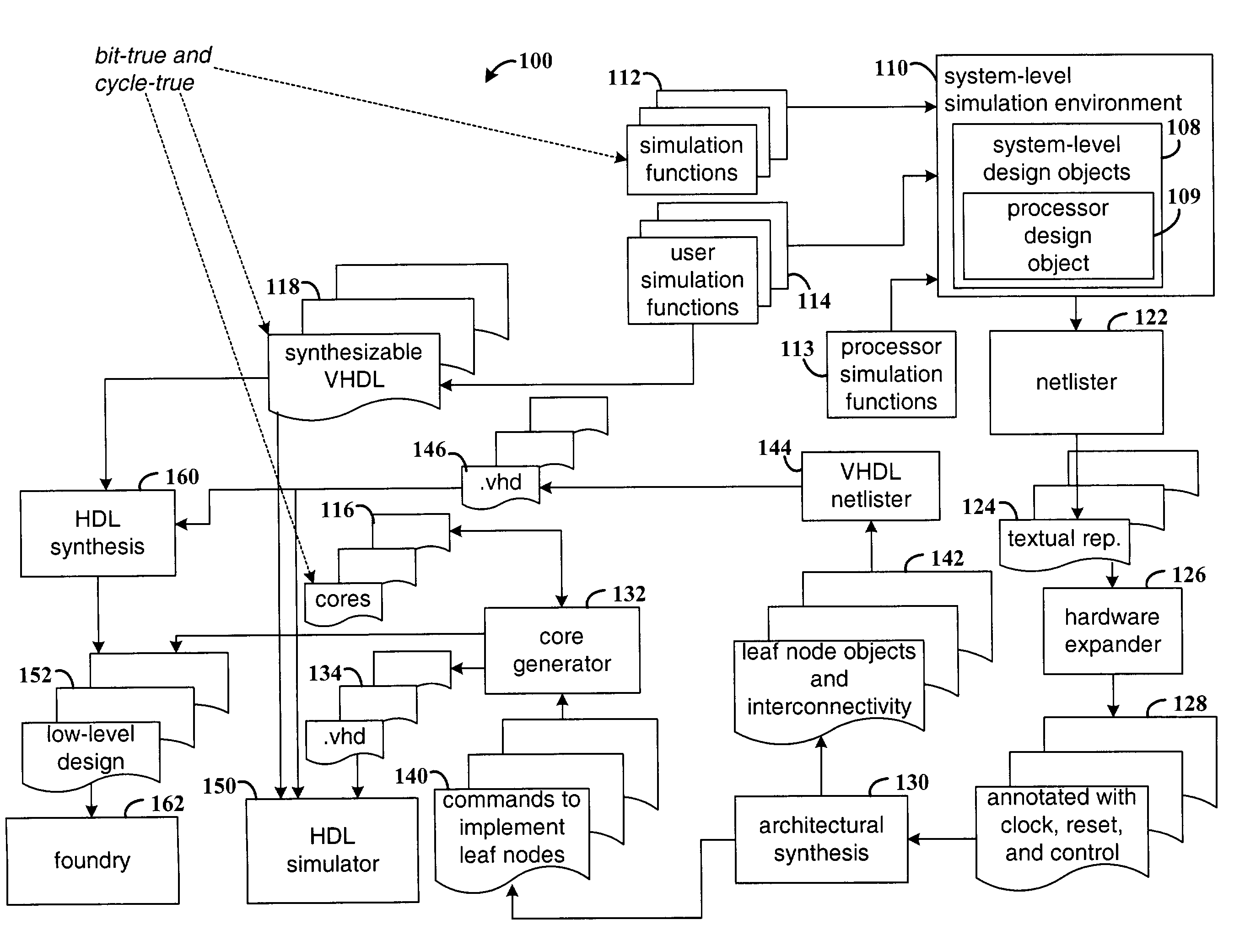
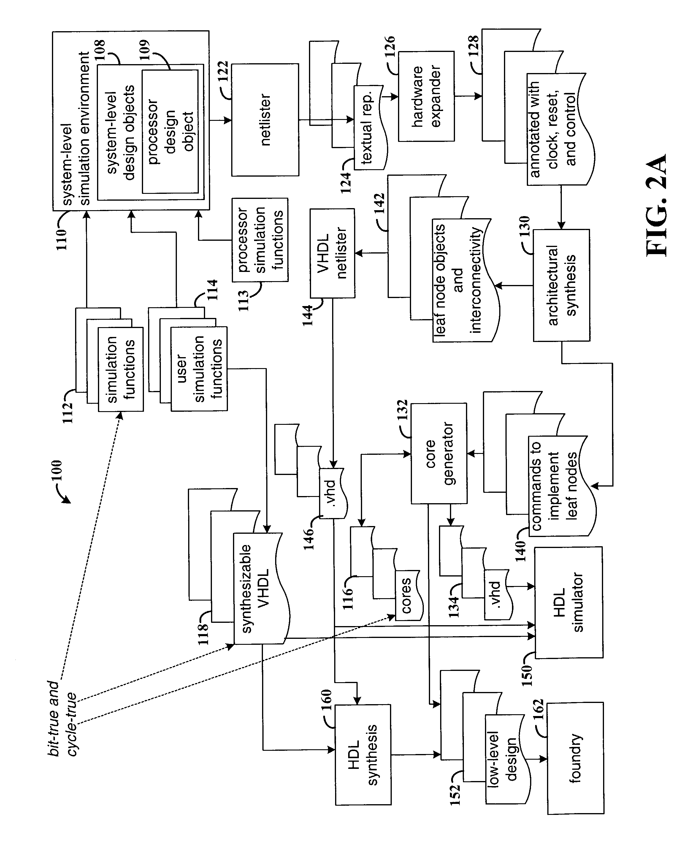
[0020]The present invention is described in terms of system-level designs for embedded systems, including digital signal processing (DSP) applications and implementations for FPGAs. It will be appreciated, however, that the various concepts described herein, along with the various embodiments of the invention, can be applied to designs other than DSP systems and to implementation technologies other than FPGAs. The invention is applicable both to visual data flow modeling environments, and to other high-level design flows, e.g., based on a programming language such as C++.

[0021]The present invention addresses the validation problem by providing a mechanism for automatically generating a hardware realization from an embedded system model, thereby removing the necessity of verifying the equivalence of the two representations. In addition, a mechanism and methodology are provided for the automatic production of a verified hardware representation from a high-level system model. In variou...


PUM


Abstract

Method and system for modeling and automatically generating an embedded system from a system-level environment. A plurality of user-selectable system-level design objects are provided in the system-level environment. Each system-level design object is defined by a system-level function and is selectable by a system-level designer. A plurality of hardware-level design objects are also provided. Each hardware-level design object is configured to generate a hardware definition of a hardware-level function. Each system-level design object maps to one or more hardware-level design objects. A processor design object is provided which defines a processor. In response to selections made by the designer, a system-level design is instantiated in a system-level design file. The system-level design includes user-selected ones of the system-level and processor design objects. The system simulates behavior of the system-level design consistent with the processor, system-level functions, and behavior of a hardware definition from the hardware-level design objects that implement the user-selected ones of the system-level design objects.

Description

[0001]This application is a continuation-in-part of U.S. patent application Ser. No. 09 / 981,503, filed Oct. 16, 2001.FIELD OF THE INVENTION[0002]The present invention generally relates to electronic circuit design tools, and more particularly to a tool that supports system-level development and simulation of an embedded system design that is bit-true and cycle-true to a hardware implementation.BACKGROUND[0003]Modern electronic systems that are implemented in application-specific integrated circuits (ASICs), field-programmable integrated circuits (FPGAs), or complex programmable logic devices (CPLDs) are often extremely complex, requiring years of effort to realize. For this reason, it is common to decompose the design problem into phases: a specification phase in which the functional requirements of the system are defined, a modeling phase in which an executable version of the functional description is realized, and an implementation phase in which a hardware realization of the syst...

Claims


Application Information

Patent Timeline
Patent Type & Authority Patents(United States)
IPC IPC(8): G06F17/50G11C29/54G06F1/04G06F1/06G06F1/08H03K19/00G06F1/00G06F17/00G11C29/00
CPCG06F17/5045G06F17/5022G06F30/30G06F30/33G06F30/3308
Inventor HWANG, L. JAMESSTROOMER, JEFFREY D.
Owner XILINX INC
Why Eureka
Try Eureka