Method and device for decoding a sequence of physical signals, reliability detection unit and viterbi decoding unit

a physical signal and sequence technology, applied in the direction of coding, amplitude demodulation, code conversion, etc., can solve the problems of insufficient reliability information, inability to provide any reliability information whatsoever on the quality of the channel decoding process, and inability to determine the reliability of the decision, so as to speed up the decoding process

Inactive Publication Date: 2006-08-01
INTEL CORP
View PDF12 Cites 17 Cited by
  • Summary
  • Abstract
  • Description
  • Claims
  • Application Information

AI Technical Summary

Benefits of technology

[0056]At least one of the memory areas may be in the form of RAM, so that the respective memory areas are integrated in the electrical circuit, thus furthermore considerably speeding up the decoding process.

Problems solved by technology

The procedure which is known from Forney has the particular disadvantage that, during the decoding process, it is not evident how reliable the decision is as to whether the respectively determined signal value actually corresponds to the originally transmitted signal value.
The method from Forney therefore provides no reliability information whatsoever on the quality of the channel decoding process.
However, it has been found that this procedure is not optimal, especially and in addition with regard to implementation in hardware.
This procedure is highly complex and, in practice, cannot be used in real time for the decoding of physical signals, in particular in the field of mobile radio.
'570, has the particular disadvantage that convergence of the Viterbi algorithm is not always guaranteed for each of the subregions which are taken into account in order to determine the further paths.

Method used


Image

  • Method and device for decoding a sequence of physical signals, reliability detection unit and viterbi decoding unit
  • Method and device for decoding a sequence of physical signals, reliability detection unit and viterbi decoding unit
  • Method and device for decoding a sequence of physical signals, reliability detection unit and viterbi decoding unit

Examples


Embodiment Construction

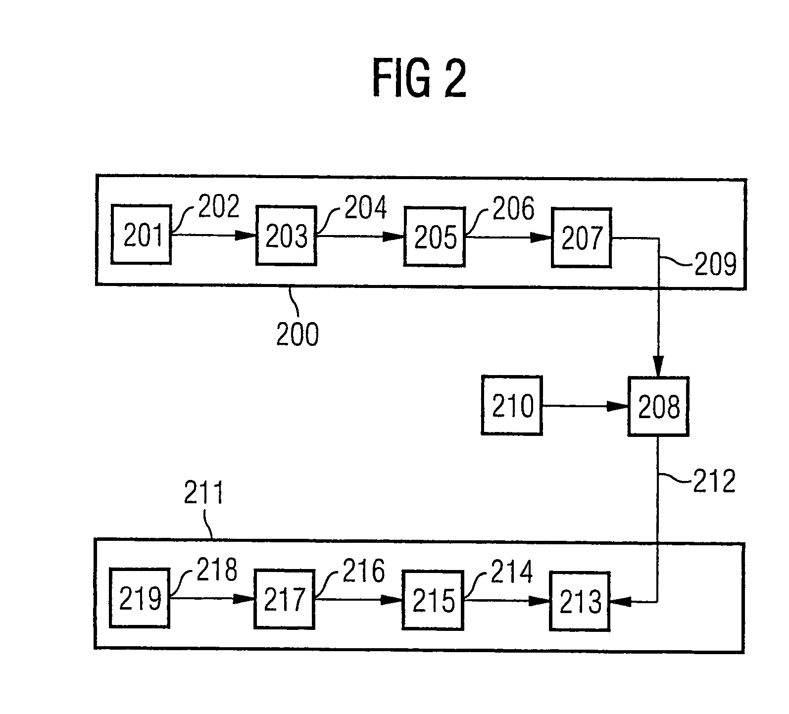
[0075]FIG. 2 shows, symbolically, a source 201 from which a message 202 is intended to be transmitted from a transmitter 200 to a sink 219 in a receiver 211.

[0076]The message 202 to be transmitted is supplied to a source coder 203, where it is compressed such that, although no information is lost, redundant information that is superfluous for the decoding of the message 202 is eliminated, and the required transmission capacity is thus reduced.

[0077]The source coder 202 emits a code word 204

uε{±1}k,  (1)

which consists of a sequence of digital values. In this case, the assumption is made for each code word 204u that each value ui, i=1, . . . , k, of each code word 204u has an equal probability of assuming a first binary value (logic “0”) or a second binary value (logic “1”).

[0078]The code word 204u is supplied to a unit for channel coding 205, in which channel coding of the code word 204u is carried out. During the channel coding process, redundant information is deliberately added to...


PUM


Abstract

A method and device for decoding a sequence of physical signals. A Viterbi algorithm is carried out a first time for all physical signals, resulting in a maximum likelihood path, wherein there is one signal value for each physical signal and which has been determined along the entire trellis according to the Viterbi algorithm. A reliability value is determined for each signal value of the maximum likelihood path. The Viterbi algorithm is then carried out a second time with the following steps: selecting one subregion of the trellis, the subregion having a partial initial signal value and a partial end signal value on the maximum likelihood path; determining one further path in that subregion of the trellis which ends at the partial end signal value of the maximum likelihood path; determining each signal value on the further path and comparing same with the corresponding signal value on the maximum likelihood path relating to the same time; depending on the comparison result, the signal value of the maximum likelihood path is allocated the reliability value determined in the previous iteration step or the minimum of this and the reliability value of the partial end signal value; shifting the subregion of the trellis by at least one time unit; and using, storing and/or outputting the determined signal values and selected reliability values associated with the signal values as the decoded sequence.

Description

BACKGROUND OF THE INVENTION[0001]1. Field of the Invention[0002]The invention relates to a method and a device for decoding a sequence of physical signals.[0003]2. Description of the Related Art[0004]A method such as this and a device such as this are known from G. D. Forney, The Viterbi-Algorithm, Proceedings of the IEEE, Vol. 61, No. 3, pages 268–278, 1973 (hereinafter referred to as “Forney”).[0005]Forney describes the principles of the so-called Viterbi algorithm.[0006]The Viterbi algorithm, which is frequently used for channel decoding of received physical signals that are subject to disturbances, determines a sequence of signal values along a so-called trellis for the received physical signals. The probability of the determined sequence of signal values corresponding to the sequence of received physical signals is in each case maximized for the sequence of signal values. The procedure which is known from Forney is used to make a decision on a binary basis for each signal value...

Claims


Application Information

Patent Timeline
Patent Type & Authority Patents(United States)
IPC IPC(8): H03M13/03G06F11/10H03M13/41H03M13/45
CPCH03M13/3961H03M13/41H03M13/4153H03M13/6502H03M13/6331H03M13/6343H03M13/4169
Inventor BECKER, BURKHARDDOETSCH, MARKUSJUNG, PETERKELLA, TIDEYAPLECHINGER, JORGRUSCITTO, ALFREDO
Owner INTEL CORP
Why Eureka
Try Eureka