Rotor assembly method

a rotor and assembly method technology, applied in the direction of magnetic circuit rotating parts, magnetic circuit shape/form/construction, magnetic bodies, etc., can solve the problems of imbalances in the rotor, additional imbalances, and limitations of the exciter rotor, and achieve the effect of significantly reducing the radial width of the lamination

Inactive Publication Date: 2006-08-08
HONEYWELL INT INC
View PDF4 Cites 7 Cited by
  • Summary
  • Abstract
  • Description
  • Claims
  • Application Information

AI Technical Summary

Benefits of technology

[0008]The present inventors have recognized that a new exciter rotor assembly can be developed that includes a hub that is supported by the generator shaft and in turn supports narrow ring-type laminations around its outer perimeter. The laminations are shrunk fit onto the hub, which is made from a strong material, is carefully manufactured to have a particular axial thickness, and in turn is shrunk fit onto the generator shaft. By incorporating such a hub in between the narrow ring-type laminations and the generator shaft, the radial width of the laminations is significantly reduced and the above-described problems associated with the manufacture and use of the laminations are alleviated.

Problems solved by technology

Such conventional exciter rotors have several limitations.
Because the structure of the rotor includes multiple laminations, and because the laminations often are made from materials that are limited in their strength, imbalances in the rotor can occur when changes or shifts in the laminations affect the relative alignment of the laminations with one another or with respect to the generator shaft.
Additional imbalances can occur when shifting or other changes in the positioning of the laminations affect the positioning of the many wire windings or rectifier circuits being supported by the laminations.
Such imbalances can create inefficiencies in the operation of the generators or risk potential failures.
Additionally, the use of laminations in the exciter rotors makes it difficult to accurately and consistently manufacture such rotors.
Slight variations in the thicknesses of the laminations of the exciter rotor can make it difficult to predictably manufacture exciter rotors having a given overall axial thickness.
Further, the complicated shape of the laminations, with their many radially protruding pole extensions and deep radial cut-outs, often renders it difficult to manufacture and assemble the laminations.

Method used


Image

  • Rotor assembly method
  • Rotor assembly method
  • Rotor assembly method

Examples


Embodiment Construction

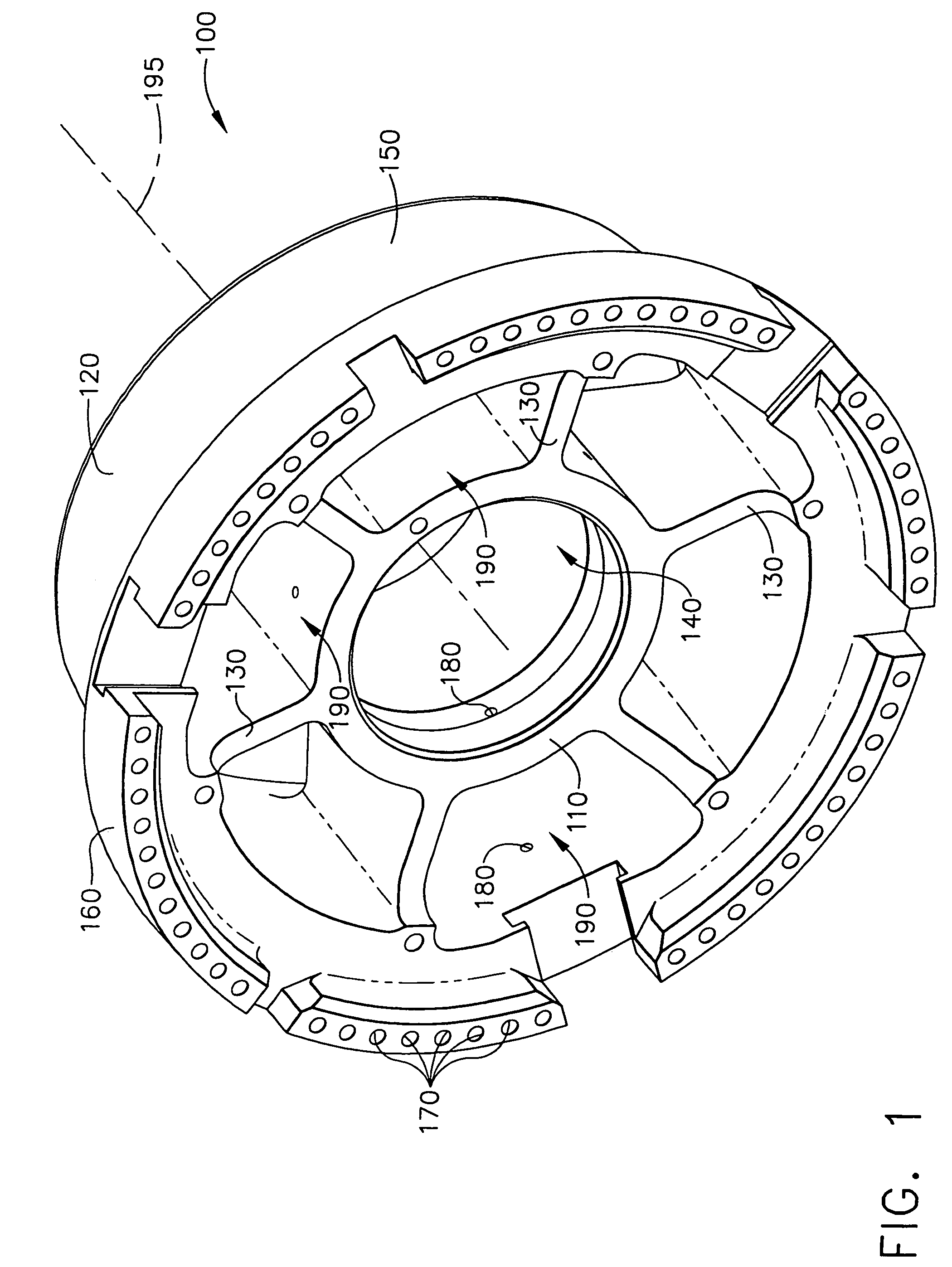
[0021]Referring to FIG. 1, a hub 100 is shown that provides the main support structure of an exciter rotor in accordance with one embodiment of the present invention. The hub 100 includes an inner cylindrical structure 110 and an outer cylindrical structure 120 that are coupled to one another by way of six spokes 130. The inner cylindrical structure 110 in particular defines a cylindrical internal cavity 140 through which a generator shaft (see FIG. 6) protrudes when a complete generator assembly (see FIG. 7) is assembled. The inner cylindrical structure 110, outer cylindrical structure 120 and spokes 130 define multiple internal cavities 190. The outer cylindrical structure 120 includes both a cylindrical support surface 150 and a retaining rim 160. As will be discussed further with respect to FIG. 2, the support surface 150 supports the laminations and wire windings of the exciter rotor. The retaining rim 160 includes multiple holes 170, which can be filled with material during th...


PUM

PropertyMeasurementUnit
outer circumferenceaaaaaaaaaa
DC currentaaaaaaaaaa
AC currentaaaaaaaaaa

Abstract

A rotor and a method of constructing a rotor are disclosed. The rotor includes a hub that is capable of being supported by a shaft that extends along an axis, a plurality of laminations, and a plurality of wire windings supported by the plurality of laminations. The hub includes an inner structure configured to support the hub relative to the shaft, an outer structure that supports the laminations, and an intermediate structure that is coupled to the inner and outer structures and supports the inner and outer structures relative to one another.

Description

CROSS REFERENCE TO RELATED APPLICATION[0001]This application is a divisional of Ser. No. 09 / 948,864 filed on Sep. 7, 2001, now U.S. Pat. No. 6,753,637.FIELD OF THE INVENTION[0002]The present invention relates to high speed generators and, more particularly, to the structure of the rotors of such generators.BACKGROUND OF THE INVENTION[0003]Generator systems that are installed in aircraft may include three separate brushless generators, namely, a permanent magnet generator (PMG), an exciter, and a main generator. The PMG includes permanent magnets on its rotor. When the PMG rotates, AC currents are induced in stator windings of the PMG. These AC currents are typically fed to a regulator or a control device, which in turn outputs a DC current. This DC current next is provided to stator windings of the exciter. As the rotor of the exciter rotates, three phases of AC current are typically induced in the rotor windings. Rectifier circuits that rotate with the rotor of the exciter rectify ...

Claims


Application Information

Patent Timeline
Patent Type & Authority Patents(United States)
IPC IPC(8): H02K15/02H02K15/10H02K1/30H02K5/22
CPCH02K1/30H02K5/225Y10T29/49073Y10T29/49009Y10T29/49011Y10T29/49012
Inventor TORNQUIST, GERALD E.LENGEL, JAMES D.BORDEN, RAYMOND W.DOHERTY, KIERAN P. J.XU, MINGCHEN, WUENFAR L.MCDOWALL, GREGOR J. S.
Owner HONEYWELL INT INC
Why Eureka
Try Eureka