
Valve apparatus for controlling mass flow, manufacturing method thereof and heat exchanger using the same

a valve apparatus and mass flow technology, applied in the direction of lighting and heating apparatus, process and machine control, instruments, etc., can solve the problems of reduced valve response speed for linear operation, high production cost of control valve apparatus, and difficulty in hermetic sealing, etc., to achieve linear and stab control, easy control of cooling (or freezing) performance, and the effect of reducing production cos

Active Publication Date: 2006-08-08
LG ELECTRONICS INC
View PDF8 Cites 5 Cited by
  • Summary
  • Abstract
  • Description
  • Claims
  • Application Information

AI Technical Summary

Benefits of technology

[0011]An object of the present invention is to provide a flow control valve apparatus that can linearly and stably control an opened area of an orifice by controlling the amount of current applied to a coil.
[0012]Another object of the present invention is to provide a manufacturing method of a flow control valve apparatus in which a supporting means for supporting a permanent magnet valve member is mass-produced precisely at a low price so as to be applied to the flow control valve apparatus by using a semiconductor batch process and micromachining technology such that its constituent parts can be miniaturized and simplified.
[0013]A further object of the present invention is to provide a heat exchanger enabling easy control of cooling (or freezing) performance by employing the flow control valve apparatus as the linear expansion valve of the heat exchanger.

Problems solved by technology

However, such a flow control valve apparatus has a high production cost due to the high price of stepping motors and has a difficulty in achieving hermetic sealing between the rotor shaft of the stepping motor and the flow channel where the valve rod is positioned.
However, this flow control valve apparatus is difficult to miniaturize due to an addition of the separate compressive space, and a valve response speed for a linear operation is reduced by using an expansion pressure due to the heating of the compressive space, so that power consumption is increased due to heat radiation.
The flow control valve using a solenoid coil has difficulty providing linear control of the fluid owing to the instable valve rod, and has problems of complicated parts and serious noise occurrence during the opening and closing operation thereof.

Method used


Image

  • Valve apparatus for controlling mass flow, manufacturing method thereof and heat exchanger using the same
  • Valve apparatus for controlling mass flow, manufacturing method thereof and heat exchanger using the same
  • Valve apparatus for controlling mass flow, manufacturing method thereof and heat exchanger using the same

Examples


Embodiment Construction

[0029]Reference will now be made in detail to the preferred embodiments of the present invention, examples of which are illustrated in the accompanying drawings.

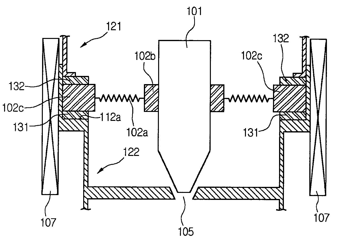
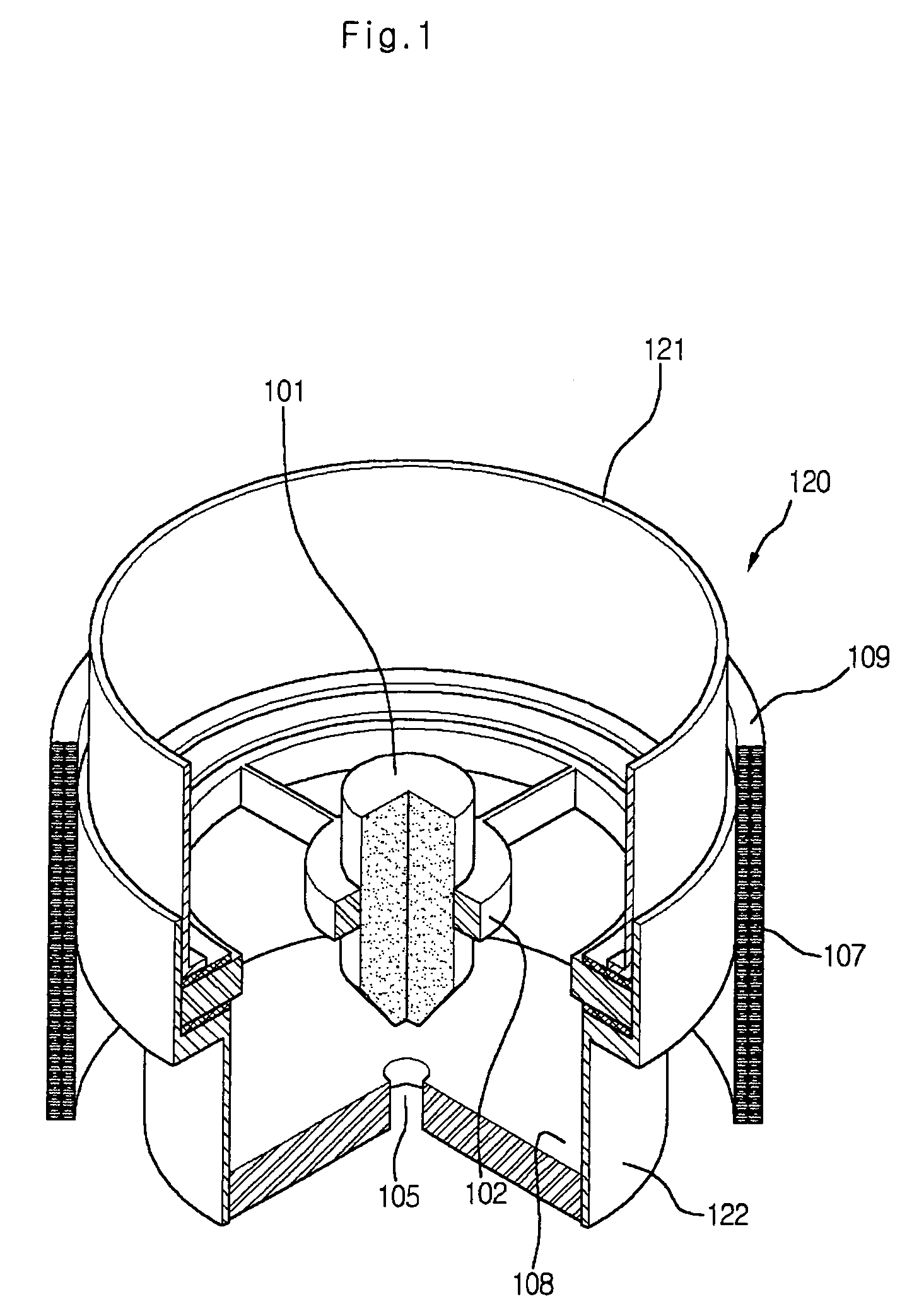
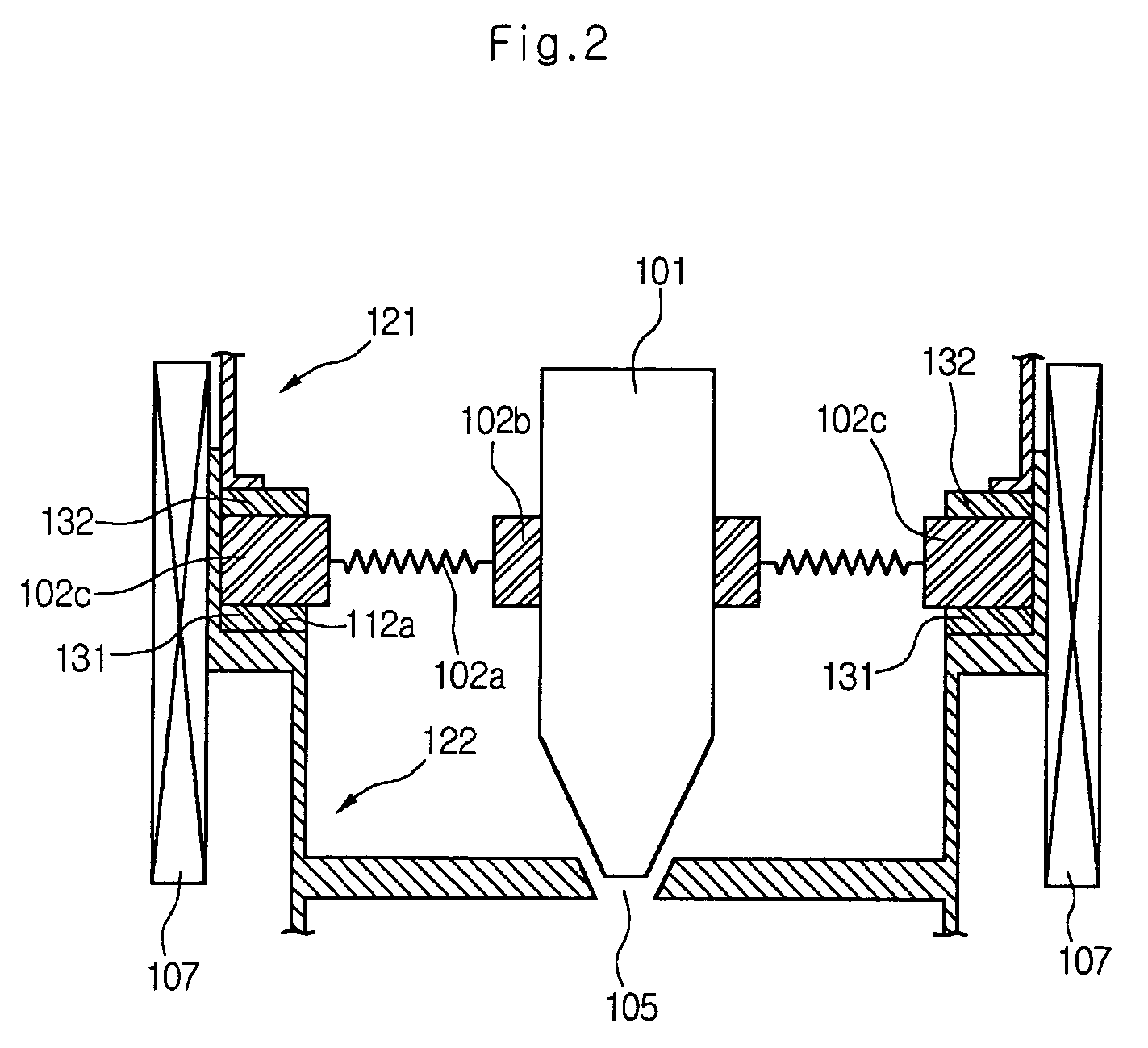
[0030]Referring to FIG. 1, an inventive flow control valve apparatus 100 is configured to include a flow channel 120 having a longitudinal axis for guiding fluid, a sealing piece 108 installed in a plane perpendicular to the longitudinal axis of the flow channel 120, and having an orifice 105 through which the fluid passes, a permanent magnet valve member 101 for opening / closing the orifice 105, a supporting member 102 for suspending the permanent magnet valve member 101, and a solenoid coil 107 to which a current for controlling displacement of the permanent magnet valve member 101 is applied.

[0031]The flow 120 channel is configured to include an upper flow channel 121 and a lower flow channel 122. It is preferable that the lower flow channel 122 is manufactured to have a diameter that is less than that of the upper flow ch...


PUM


Abstract

A flow control valve apparatus, a manufacturing method thereof and a heat exchanger using the same. The flow control valve apparatus includes: a flow channel having a longitudinal axis comprised of an upper flow channel and a lower flow channel, for guiding a fluid; sealing means installed in a plane perpendicular to the flow channel and having an orifice through which the fluid passes; opening / closing means for controlling opening / closing of the orifice; and applying means installed along an outer circumference of the flow channel and to which a current may be applied for controlling the opening / closing of the orifice. According to the inventive flow control valve apparatus, the displacement of the permanent magnet valve member is varied using the current applied to the solenoid coil, thereby linearly controlling the opened area of the orifice and / or performing the opening / closing operation of the orifice. The valve apparatus can be miniaturized at a low price. By applying the valve apparatus to a heat exchanger, its cooling efficiency can be controlled easily.

Description

[0001]This Nonprovisional application claims priority under 35 U.S.C. § 119(a) on Patent Application No. 25004 / 2003 filed in Korea on Apr. 21, 2003, the entire contents of which are hereby incorporated by reference.BACKGROUND OF THE INVENTION[0002]1. Field of the Invention[0003]The present invention relates to a flow control valve apparatus, and more particularly, to a flow control valve apparatus that can control flow depending on a linear displacement of a permanent magnet valve lid using a current manufacturing method thereof, and a heat exchanger using the same.[0004]2. Description of the Related Art[0005]Because the flow control valve apparatus for controlling flow flowing through a flow channel is applicable to many industrial fields (ex. refrigerator, etc.), research on the flow control valve apparatus has recently been actively performed.[0006]In general, a flow control valve apparatus controls flow by moving a pin shaped valve rod from an orifice by a predetermined distance...

Claims


Application Information

Patent Timeline
IPC IPC(8): F25B41/04F16K31/02F15C5/00F16K31/06F16K31/08F16K99/00F25B41/06G05D7/06
CPCF15C5/00F16K31/0651F16K31/0655F16K31/082F16K99/0001F16K99/0046F25B41/062F16K99/0009Y02B30/72F16K2099/0074F16K2099/0076F25B2341/0653Y02B30/70F25B41/35F25B41/345
Inventor YEE, YOUNG JOO
Owner LG ELECTRONICS INC
Learn More