
Flow control valve and method of controlling rotation in a downhole tool

a flow control valve and tool technology, applied in the direction of machines/engines, positive displacement liquid engines, borehole/well accessories, etc., can solve the problems of not being able to accurately control the rotation speed of the hydraulic motor downhole with sufficient accuracy at surface, and not being able to maintain the optimal surface rotation rate. the effect of flow

Inactive Publication Date: 2006-08-08
BJ SERVICES CO
View PDF14 Cites 37 Cited by
  • Summary
  • Abstract
  • Description
  • Claims
  • Application Information

AI Technical Summary

Benefits of technology

"The invention is about a device and method for controlling the speed of a hydraulic motor, which is used to power tools in drilling and other downhole operations. The device is a flow control valve that is connected to the motor and can adjust the flow of fluid to control the speed of the motor. This allows for better control and optimization of the motor's performance. The valve is controlled by a pump assembly that adjusts the fluid flow based on the motor's speed. The device can be used in drilling and de-scaling tools, and it can be easily attached to a hydraulic motor for downhole tools. The technical effects of this invention include improved control and optimization of hydraulic motor performance, better communication between the surface and the downhole tools, and reduced wear and tear on downhole tools."

Problems solved by technology

For instance, optimum life and drilling performance is a significant concern when utilizing a mud motor for drilling or milling, especially with two-phase fluids, as excessive rates of rotation or stalling may occur due to the compressibility of the power fluid.
However, in prior art systems, it is not generally possible to maintain the optimal rate of rotation at surface.
However, the actual speed of the hydraulic motor downhole is not known with sufficient accuracy at surface to accurately control the rotation in this way.
Two-phase flow exacerbates this problem.
Thus, it is difficult to sufficiently control the rotational speed of the hydraulic motor and thus of the downhole tool.
It is also known that in prior art systems, it is tedious, difficult, or even impossible to initially set up the tool such that it will operate at a predetermined rate at bottom hole conditions (pressure, temperature, etc.) and for a known or given flow rate.
As such, the hydraulic motors may rotate excessively, causing damage to themselves or the tools they are rotating.
Alternatively, the hydraulic motors and the downhole tools attached thereto may rotate at a less-than-optimal rate.
Additionally, there are competing demands on flow rate of the circulating or working fluid.
However well bore conditions are not always known with sufficient certainty, especially bottom hole pressure, to ensure the downhole hydraulic motor rotates at or near the optimal, predetermined level.
Therefore it may be difficult to appropriately predict circulating flow rates under the conditions set up for the hydraulic motor and downhole tool, such as a scale removal unit or a drill bit.
However, this has been found to be problematic, since the values of such parameters are not initially known with certainty.

Method used


Image

  • Flow control valve and method of controlling rotation in a downhole tool
  • Flow control valve and method of controlling rotation in a downhole tool
  • Flow control valve and method of controlling rotation in a downhole tool

Examples


examples

[0094]The following examples are included to demonstrate preferred embodiments of the invention. It should be appreciated by those of skill in the art that the techniques disclosed in the examples which follow represent techniques discovered by the inventors to function well in the practice of the invention, and thus can be considered to constitute preferred modes for its practice. However, those of skill in the art should, in light of the present disclosure, appreciate that many changes can be made in the specific embodiments which are disclosed and still obtain a like or similar result without departing from the spirit and scope of the invention.

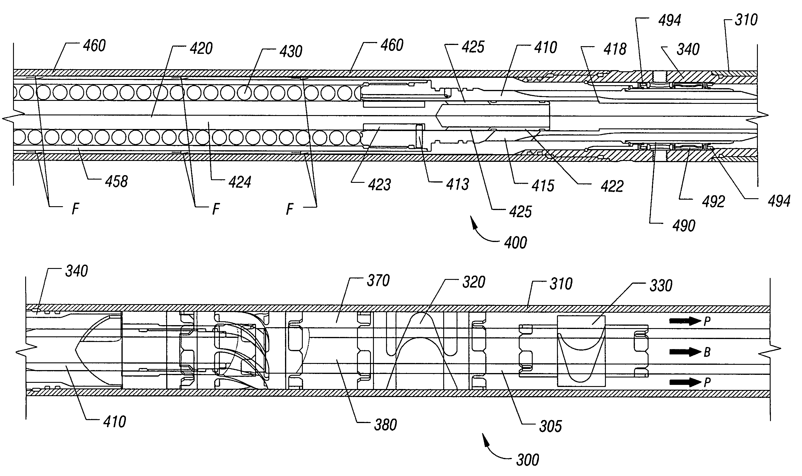
[0095]Examples follow. For the ROTO-JET example, and when operating at the predetermined motor speed of rotation of 400 rpm, the system may be designed for the Flow Control Valve 400 to divert 20% of the working fluid to bypass flow in the bypass flow path 380 of the turbine shaft 305, with 80% of the fluid remaining in the power fluid flo...


PUM


Abstract

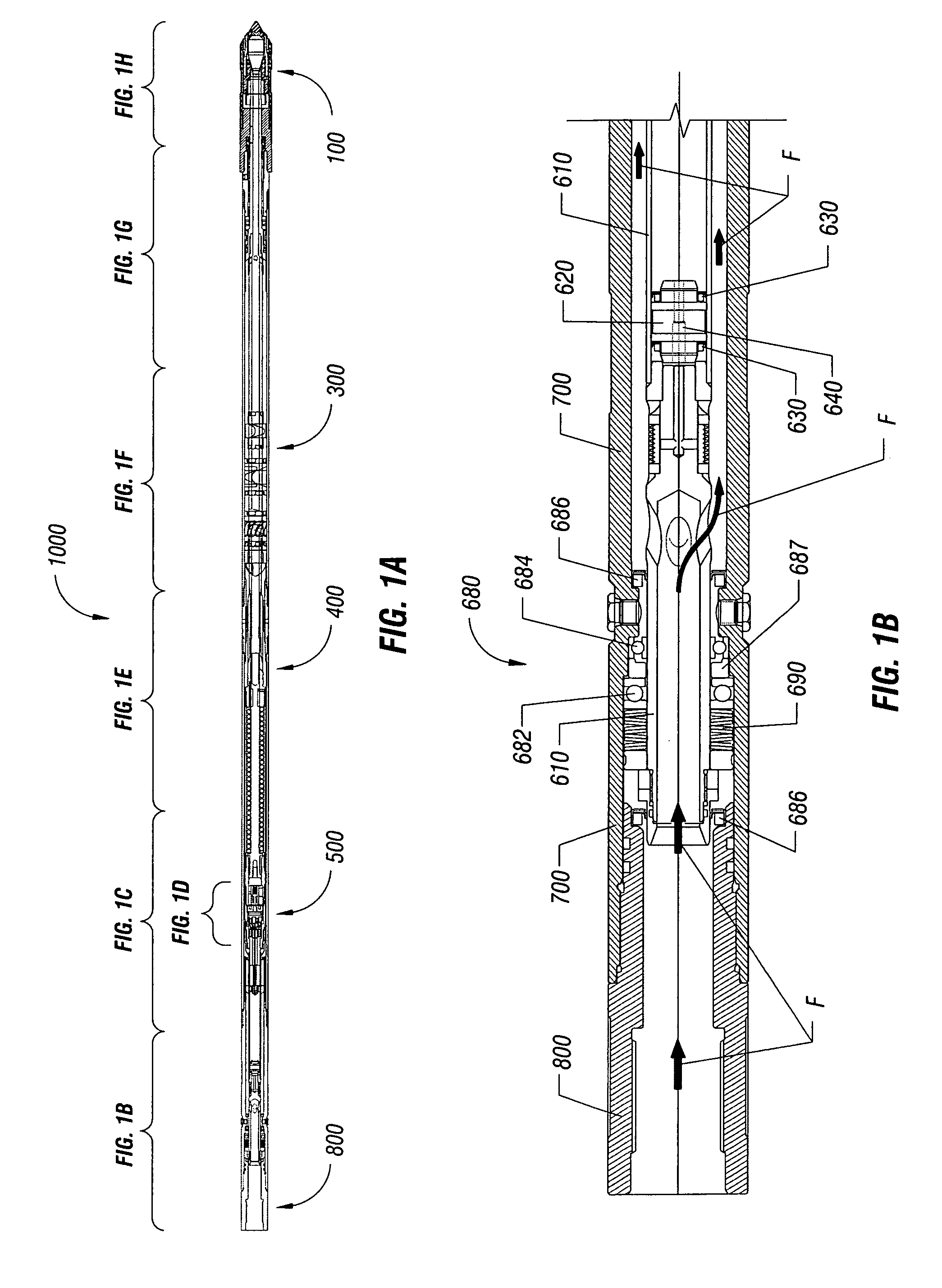
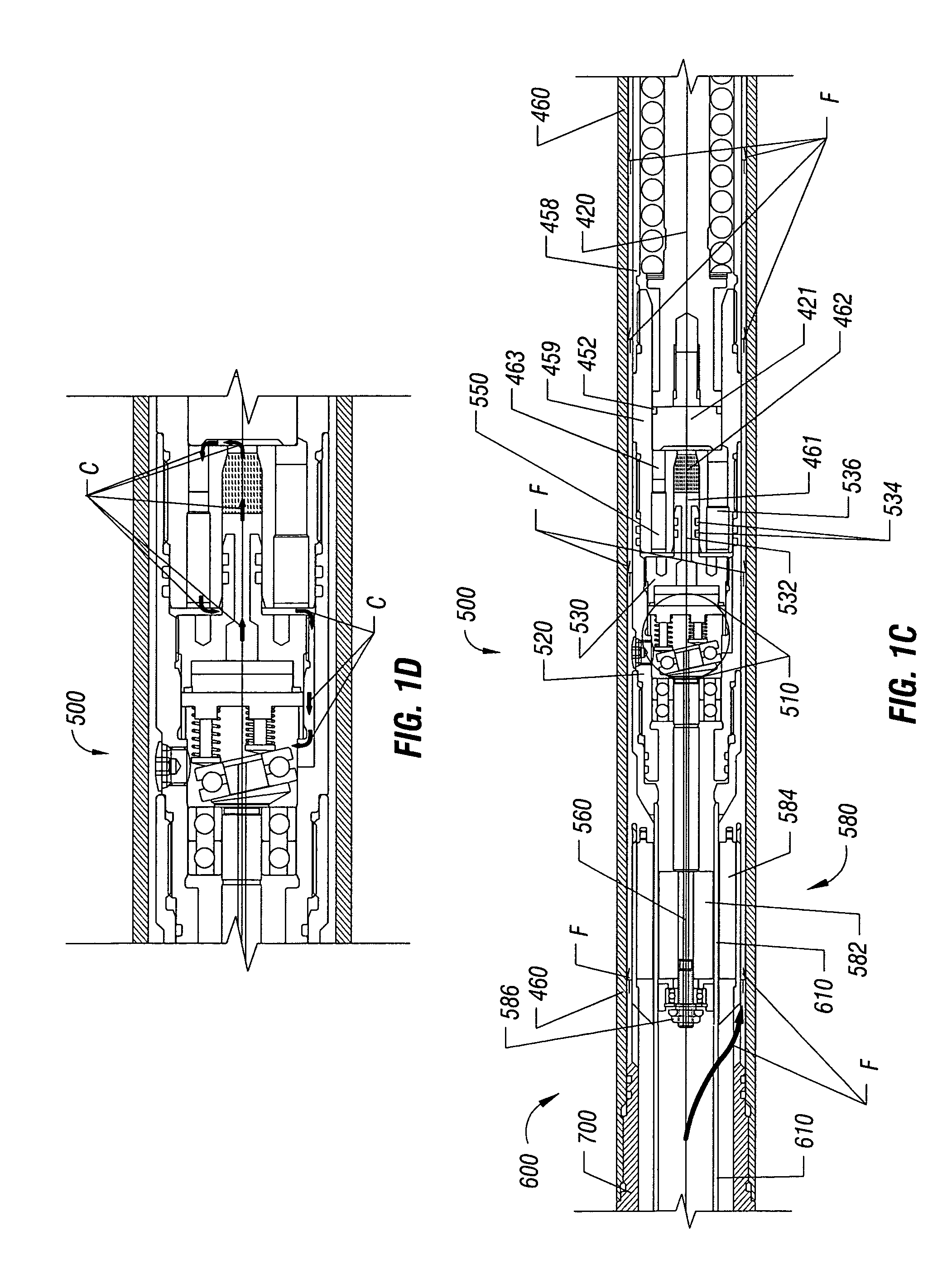
A flow control valve is disclosed for controlling the rotation of a hydraulic motor, such as a turbine, a mud motor, for example, having an element that rotates in response to power fluid. The valve disclosed may include a valve housing and a valve piston, each having a port, moveable relative to one another. When the ports at least partially align, bypass flow is generated which acts to decrease the speed of rotation of the element, such as a turbine shaft. An energizer, such as a pump assembly, is further described which is adapted to move the valve housing or the valve piston in response to the speed of rotation, such that bypass flow is a function of the motor speed (i.e. speed of rotation of the element). A bottom hole assembly including a flow control valve and a method of controlling the rotation of a downhole tool are also described.

Description

BACKGROUND OF THE INVENTION[0001]1. Field of the Invention[0002]The present invention relates to performing downhole operations in wellbores in the field of oil and gas recovery. More particularly, this invention relates to a device adapted to improve the control of the speed of a downhole hydraulic motor.[0003]2. Description of the Related Art[0004]In the oil and gas industry, various operations utilize the rotation of a downhole tool or apparatus. For instance, downhole tools such as drill bits, mills, and scale removal devices are rotated downhole to perform a given operation. A downhole hydraulic motor, such as positive displacement motors (PDMs) and turbines may be used to generate this rotational power.[0005]Generally, a pump at surface injects a working fluid downhole through a drill string, work string, or coiled tubing string. The work fluid is delivered to the downhole hydraulic motor to provide rotational movement to the downhole tool or apparatus attached thereto, such a...

Claims


Application Information

Patent Timeline
Patent Type & Authority Patents(United States)
IPC IPC(8): E21B4/02E21B4/00E21B23/08E21B37/04E21B44/00F03B13/02F03B15/12F04B47/08F04B49/035
CPCE21B4/02E21B23/08E21B37/04E21B44/00
Inventor RAVENSBERGEN, JOHN EDWARDPIKE, DONBRUNSKILL, DOUG
Owner BJ SERVICES CO
Learn More