Honeycomb structure and assembly thereof

a honeycomb and structure technology, applied in the field of honeycomb structure, can solve the problems of large thermal stress and cracks, non-uniform temperature distribution, and insufficient relaxation of stress applied thereto

Inactive Publication Date: 2006-08-08
NGK INSULATORS LTD
View PDF22 Cites 22 Cited by
  • Summary
  • Abstract
  • Description
  • Claims
  • Application Information

AI Technical Summary

Benefits of technology

[0012]In the second aspect, the material B having compressive elasticity is preferably a ceramic fiber-made mat, further preferably a heat-intumescent mat containing vermiculite, more preferably a non-intumescent mat composed mainly of alumina or mullite. The honeycomb structure assembly is preferably a canned structure obtained by a stuffing method, a tourniquet method, a clamshell method or a swaging method. Further, the honeycomb structure assembly is preferably obtained by loading a catalyst on honeycomb segments and then accommodating the catalyst-loaded honeycomb segments in a metallic container. Alternatively, the honeycomb structure assembly is preferably obtained by accommodating honeycomb segments in a metallic container and then loading a catalyst on the honeycomb segments.

Problems solved by technology

In a honeycomb structure used for such a purpose, a sharp temperature change of exhaust gas and local heating make non-uniform the temperature distribution inside the honeycomb structure, and there have been problems such as crack generation in the honeycomb structure and the like.
When the honeycomb structure is used particularly as a filter for trapping a particulate matter in an exhaust gas emitted from a diesel engine, it is necessary to burn the fine carbon particles deposited on the filter to remove the particles and regenerate the filter and, in that case, high temperatures are inevitably generated locally in the filter; as a result, large thermal stress and cracks tend to be generated.
Therefore, even with honeycomb structures such as mentioned above, when a sharp temperature change of inflow gas takes place, and a local heat of reaction, a local heat of combustion, etc., becomes larger during use, it is possible that the thermal stress applied thereto may not be sufficiently relaxed, cracks may appear therein and, in an extreme case, for example, the honeycomb structure may begin to disintegrate and break into fine pieces due to vibration.

Method used


Image

  • Honeycomb structure and assembly thereof
  • Honeycomb structure and assembly thereof
  • Honeycomb structure and assembly thereof

Examples


example 1

[0045]A silicon carbide powder was used as a raw material. Thereto were added methyl cellulose, hydroxypropoxyl methyl cellulose, a surfactant and water to prepare a plastic material. This puddle (mud) was subjected to extrusion molding, and the resulting extrudate was dried using a microwave and hot air.

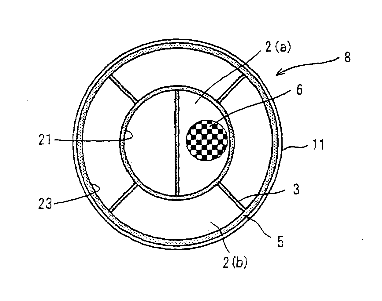
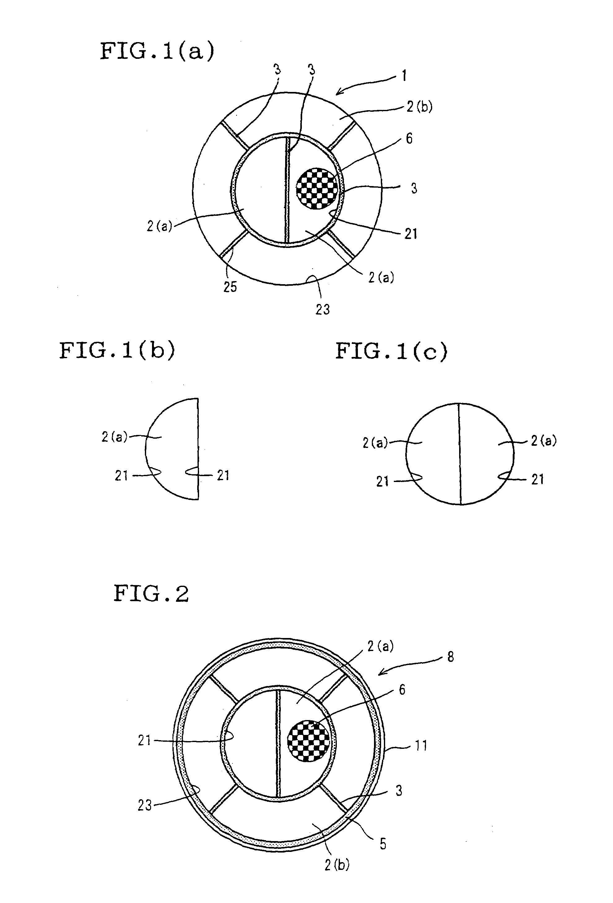
[0046]Then, the passages of the extrudate were plugged alternately at each end face of the extrudate with a sealant made of the same material as for the honeycomb structure to be obtained, in such a way that each end face of extrudate had a checkerboard pattern appearance. Then, the resulting material was heated for debindering in a N2 atmosphere and then fired in an Ar atmosphere to obtain four honeycomb segments 2(b) having an outer diameter of 144 mm, an inner diameter of 73 mm and a length of 152 mm and two half-cylindrical honeycomb segments 2(a) having a diameter of 72 mm and a length of 152 mm. These six honeycomb segments 2(a) and 2(b) were bonded into one piece by providing...

example 2

[0047]The five honeycomb segments in total produced in the same manner as in Example 1 as shown in FIG. 9(b), i.e. two quadratic prism-shaped honeycomb segments 2(c) having a size of 30 mm×30 mm×152 mm, one honeycomb segment 2(d) and two honeycomb segments 2(e), were bonded using an adhesive 7 which was a mixture of colloidal silica, an alumina fiber and water, followed by drying, to produce four bonded honeycomb segments 9(a). Similarly, four quadratic prism-shaped honeycomb segments 2(c) having a size of 30 mm×30 mm×152 mm were bonded using an adhesive 7 which was a mixture of colloidal silica, an alumina fiber and water, followed by drying, to produce one bonded honeycomb segment 9(b), which does not constitute the outermost peripheral surface of the honeycomb structure. Then, the four bonded honeycomb segments 9(a) and the one bonded honeycomb segment 9(b) were bonded into one piece by providing a ceramic fiber-made non-intumescent mat 3 on the side surface 21 of the bonded hone...

example 3

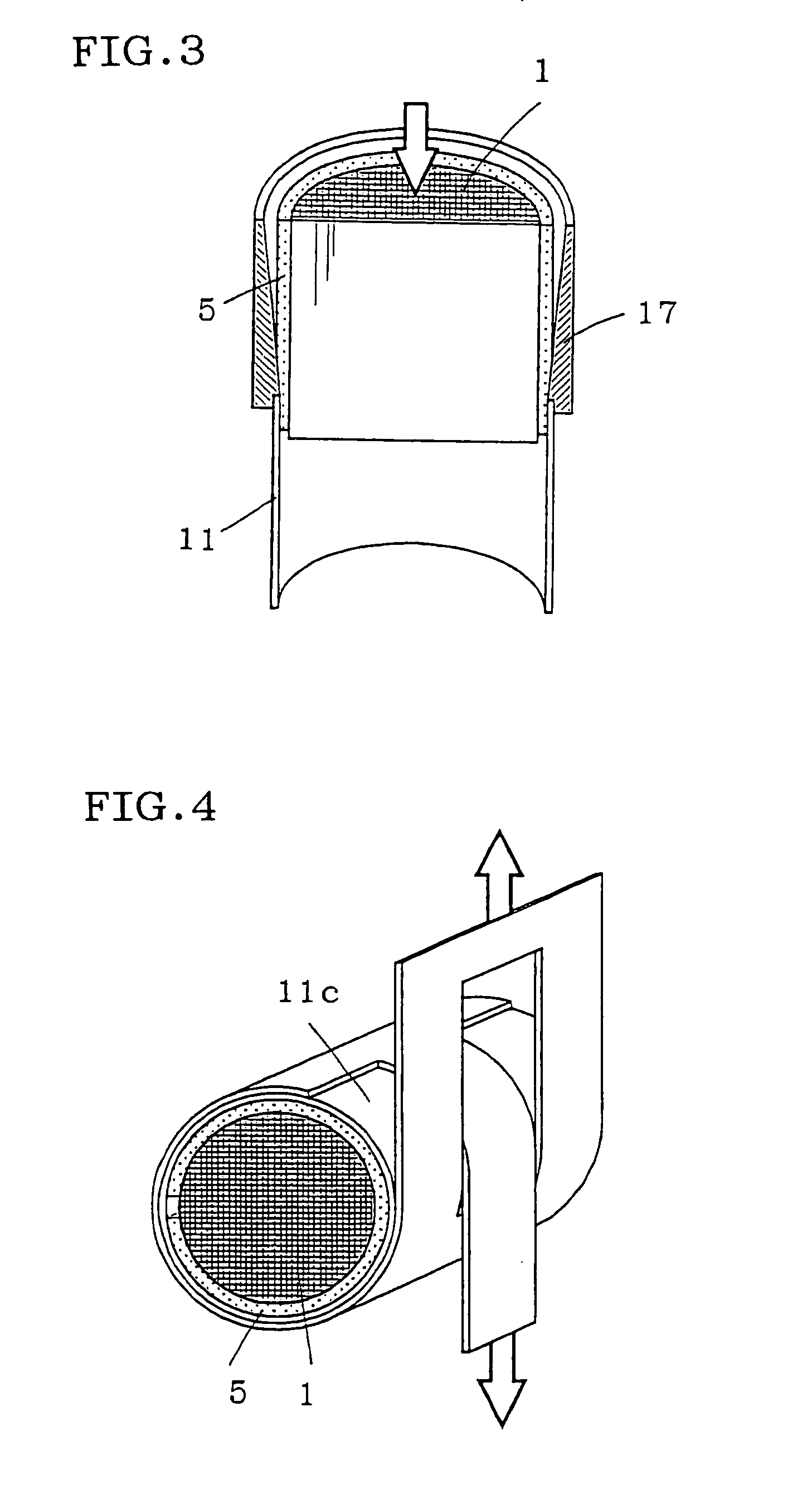
[0048]Four bonded honeycomb segments 9(a) were produced in the same manner as in Example 2. Two quadratic prism-shaped bonded honeycomb segments 9(c) having a size of 30 mm×60 mm×152 mm, shown in FIG. 10(b), were produced by bonding two quadratic prism-shaped honeycomb segments 2(c) having a size of 30 mm×30 mm×152 mm using an adhesive 7 which was a mixture of colloidal silica, an alumina fiber and water, followed by drying the bonded material. These six bonded honeycomb segments 9(a) and 9(c) were bonded into one piece by providing a ceramic fiber-made non-intumescent mat 3 on the side surfaces 21 of the bonded materials 9(c) and at the space between the side surfaces 25 of each two adjacent bonded materials 9(a) and using a double sided tape, to obtain a honeycomb structure 1 show in FIG. 10(a). The same ceramic fiber-made non-intumescent mat as mentioned above was wound around the outermost peripheral surface 23 of the honeycomb structure 1; the resulting material was stuffed in ...


PUM

PropertyMeasurementUnit
thicknessaaaaaaaaaa
lengthaaaaaaaaaa
diameteraaaaaaaaaa

Abstract

A honeycomb structure obtained by bonding, into one piece, a plurality of honeycomb segments (2) each having a plurality of passages (6) surrounded by cell walls and extending in the axial direction of the segment. In the honeycomb structure, a material A (3) having compressive elasticity is provided between a side surface (21) of at least one honeycomb segment [2(a)] not constituting the outermost peripheral surface (23) of the honeycomb structure (1) and a side surface of the honeycomb segment [(2(b)) adjacent thereto. A honeycomb structure assembly (8) obtained by providing a material B (5) having compressive elasticity on the outermost peripheral surface (23) of the honeycomb structure (1) in a compressed state and thereby compression-holding the resulting honeycomb structure in a metallic container (11). A honeycomb structure using materials having compressive elasticity (B) is resistant to breakage, and has superior durability and reliability, by reducing the thermal stress generated therein during use by a sharp temperature change of inflow gas, a local heat of reaction and a local heat of combustion.

Description

BACKGROUND[0001]1. Technical Field[0002]The present invention relates to a honeycomb structure used in, for example, a catalyst carrier utilizing a catalytic action, for use in an internal combustion engine, a boiler, a chemical reactor, a fuel cell reformer, etc., a filter for trapping fine particles present in an exhaust gas, and to an assembly thereof. More particularly, the present invention relates to a honeycomb structure that is resistant to breaks when exposed to a thermal stress during its use, as well as to an assembly thereof.[0003]2. Background Art[0004]Honeycomb structures are in use in, for example, a carrier for a catalyst having a catalytic action, for use in an internal combustion engine, a boiler, a chemical reactor, a fuel cell reformer, etc., and a filter for trapping fine particles present in an exhaust gas, particularly fine particles emitted from a diesel engine.[0005]In a honeycomb structure used for such a purpose, a sharp temperature change of exhaust gas a...

Claims


Application Information

Patent Timeline
Patent Type & Authority Patents(United States)
IPC IPC(8): B32B3/12B01D53/34B01J21/04F01N3/02B01D39/14B01D39/20B01D46/00B01D46/24B01D53/86B01D53/88B01D53/94B01J35/04F01N3/021F01N3/28F01N13/04F01N13/18H01M8/06
CPCB01D39/2068B01D46/4218B01D53/885B01D53/94C04B37/005C04B38/0016F01N3/2825F01N3/2828F01N3/2853F01N3/2857F01N13/18F01N13/017B01D46/2422Y10T428/1234C04B2111/00793C04B2235/5224C04B2235/5228C04B2237/062C04B2237/064C04B2237/34C04B2237/341C04B2237/343C04B2237/346C04B2237/348C04B2237/365C04B2237/368C04B2237/595C04B2237/74F01N2260/10F01N2330/06F01N2330/30F01N2330/48F01N2350/02F01N2450/28F01N2470/08Y10T428/24149
Inventor HIJIKATA, TOSHIHIKO
Owner NGK INSULATORS LTD
Why Eureka
Try Eureka