Drive unit and vehicle equipped therewith

a technology of drive unit and drive unit, which is applied in the direction of fuel cells, electric energy management, electric devices, etc., can solve the problems of reducing the life of the switch, increasing the load applied to the first switch, and increasing the load applied to the secondary battery and the electrolyzer, and achieves the effect of high fuel cell operating efficiency

Inactive Publication Date: 2006-08-08
TOYOTA JIDOSHA KK
View PDF20 Cites 17 Cited by
  • Summary
  • Abstract
  • Description
  • Claims
  • Application Information

AI Technical Summary

Benefits of technology

[0008]In a drive unit provided with a charge / discharge portion and a fuel cell connected in parallel to a drive circuit for driving a motor without the intervention of a voltage converter, and in a vehicle equipped with the drive unit, it is an object of the invention to maintain high operating efficiency of the fuel cell even if the fuel cell is not cut off from the drive circuit during regenerative control of the fuel cell.
[0011]In the drive unit of the aforementioned aspect, when regenerative control of the motor is performed, the charge / discharge portion having at least one capacitor whose working voltage is set such that a voltage in a fully charged state stays above an inter-open-terminal voltage of the fuel cell is charged with regenerative power obtained. At this moment, the inter-terminal voltage of the charge / discharge portion becomes higher than the inter-open-terminal voltage of the fuel cell in some cases. However, since the diode is installed and oriented in such a direction that the fuel cell can charge the charge / discharge portion, no reverse current flows through the fuel cell. As a result, there is no need to cut the fuel cell off from the drive circuit during regenerative control of the motor. In the drive unit of the invention, when power running control of the motor is performed after regenerative control of the motor as mentioned above, the motor is driven by an output from the charge / discharge portion if the inter-terminal voltage of the charge / discharge portion is higher than the inter-open-terminal voltage of the fuel cell, and by outputs from the fuel cell and the charge / discharge portion if the inter-terminal voltage of the charge / discharge portion has dropped to the inter-open-terminal voltage of the fuel cell. That is, a phenomenon that can be caused by connection of the fuel cell when the inter-terminal voltage of the charge / discharge portion is lower than the inter-open-terminal voltage of the fuel cell, namely, a phenomenon of the flow of a large current between the fuel cell and the charge / discharge portion can be avoided.
[0014]In addition, the drive unit of the aforementioned aspect may further comprise a cut-off portion that can cut the fuel cell off from the drive circuit, and the drive control portion may control the cut-off portion such that the fuel cell is not cut off from the drive circuit when motive power is input to or output from the drive shaft by the motor. In this construction, the cut-off portion can be inhibited from deteriorating due to an increase in the load applied thereto. The drive control portion may also control the cut-off portion such that the fuel cell is not cut off from the drive circuit either when regenerative control of the motor is performed.
[0015]Furthermore, in the drive unit of the aforementioned aspect, the charge / discharge portion may be composed of a plurality of capacitors that are connected in parallel. The charge / discharge portion may have a connection switch for connecting or disconnecting at least one of the capacitors. In this construction, only one or some of the capacitors can be used. In addition, the drive unit of the aforementioned aspect may further comprise a voltage detection portion that detects an inter-terminal voltage of the charge / discharge portion, and the drive control portion may control the connection switch such that the at least one of the capacitors is disconnected if regenerative control of the motor is performed, and such that the at least one of the capacitors that has been disconnected is connected if an inter-terminal voltage detected by the voltage detection portion becomes higher than an inter-open-terminal voltage of the fuel cell by a predetermined voltage with the at least one of the capacitors having been disconnected. In this construction, a state in which the inter-terminal voltage of the charge / discharge portion is between the inter-open-terminal voltage of the fuel cell and the predetermined voltage can be passed quickly. Therefore, in the case where a fuel cell to be used does not exhibit particularly high operating efficiency when being operated at a voltage between the inter-open-terminal voltage and the predetermined voltage, suppression of a fall in operating efficiency of the fuel cell, namely, enhancement of operating efficiency of the fuel cell can be achieved.

Problems solved by technology

In the case where regenerative control of the motor is frequently performed, the more complicated the control becomes, the more the load applied to the first switch increases.
Therefore, if the drive unit becomes complicated, both the secondary battery and the electrolyzer become complicated.
Such a large current causes an inconvenience such as reduction of a life span of the switch.

Method used


Image

  • Drive unit and vehicle equipped therewith
  • Drive unit and vehicle equipped therewith
  • Drive unit and vehicle equipped therewith

Examples


Embodiment Construction

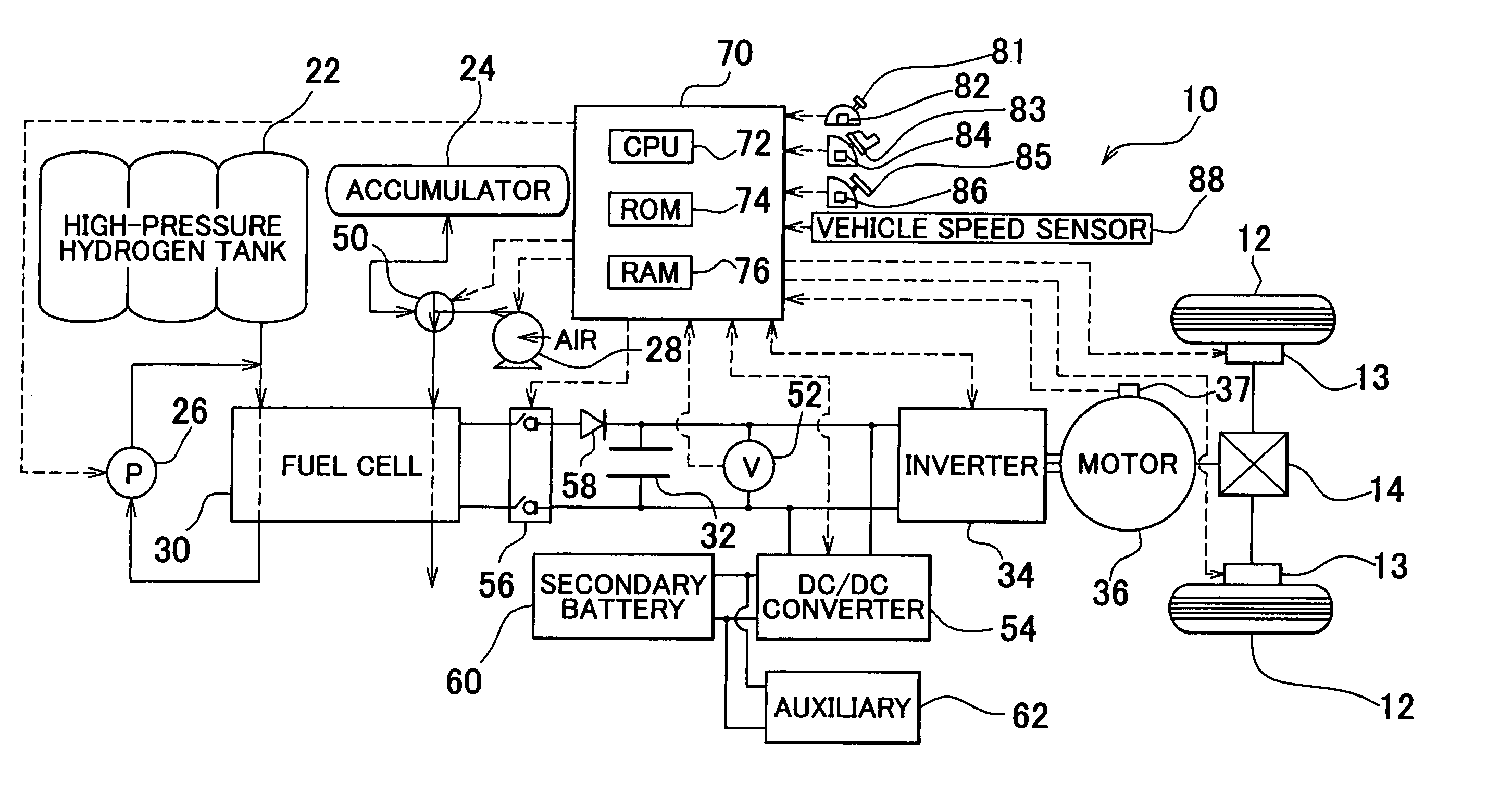
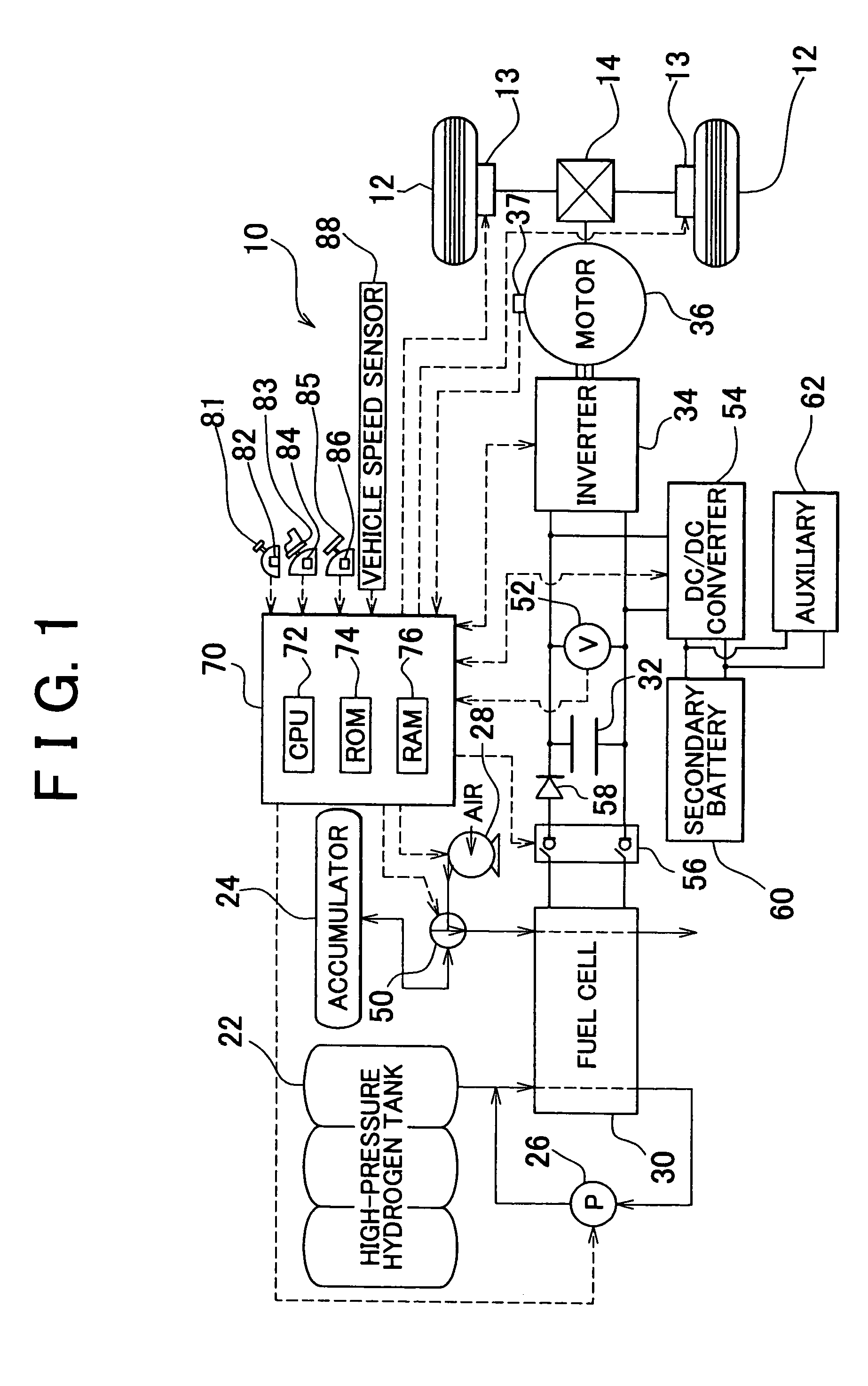
[0026]Next, modes of implementing the invention will be described with reference to embodiments thereof. FIG. 1 is a block diagram showing the overall construction of an electric vehicle 10 in accordance with one embodiment of the invention. As shown in FIG. 1, the electric vehicle 10 of the embodiment is provided with a fuel cell 30, a capacitor 32, an inverter 34, a traction motor 36, and an electronic control unit 70. The fuel cell 30 generates electricity using hydrogen gas and oxygen contained in air. The hydrogen gas is a fuel gas supplied from a high-pressure hydrogen tank 22 and caused to circulate by a circulation pump 26, and the oxygen is supplied from an air compressor 28 and an accumulator 24 via a change-over valve 50. The capacitor 32 is connected in parallel to the fuel cell 30 via a circuit breaker 56. The inverter 34 converts direct-current power transmitted from the fuel cell 30 and the capacitor 32 into three-phase alternating current power. The traction motor 36...


PUM

PropertyMeasurementUnit
temperatureaaaaaaaaaa
voltageaaaaaaaaaa
electric poweraaaaaaaaaa

Abstract

A drive unit of the invention comprises a motor that can input / output motive power to / from a drive shaft, a drive circuit that performs drive control of the motor, a fuel cell that is connected to the drive circuit without the intervention of a voltage converter such that electric power can be output, a charge / discharge portion that is connected to the fuel cell in parallel and to the drive circuit such that electric power can be output and that has at least one capacitor whose voltage in a fully charged state is higher than an inter-open-terminal voltage of the fuel cell, a diode that is installed between the fuel cell and the charge / discharge portion such that electric power can be output only in a direction from the fuel cell to the charge / discharge portion, and a drive control portion that controls the drive circuit such that drive control of the motor is performed on the basis of required motive power to be transmitted to the drive shaft. This drive unit is characterized in that the drive circuit performs drive control of the motor through the output of electric power from the charge / discharge portion or the output of electric power from the charge / discharge portion and the fuel cell.

Description

INCORPORATION BY REFERENCE[0001]The disclosure of Japanese Patent Application No. 2003-036757 filed on Feb. 14, 2003 including the specification, drawings and abstract is incorporated herein by reference in its entirety.BACKGROUND OF THE INVENTION[0002]1. Field of the Invention[0003]The invention relates to a drive unit and a vehicle equipped therewith.[0004]2. Description of the Related Art[0005]Heretofore, there has been proposed a drive unit of this type wherein a fuel cell, a secondary battery, a large-capacitance capacitor, and an electrolyzer are connected in parallel to a drive circuit for driving a motor without the intervention of a voltage converter and wherein a first switch for cutting the fuel cell and the secondary battery off from the drive circuit and a second switch for cutting the electrolyzer off are provided (Japanese Patent Application Laid-Open No. 6-253409 (FIGS. 1 and 2, page 4)). The first and second switches are on and off respectively during normal operati...

Claims


Application Information

Patent Timeline
Patent Type & Authority Patents(United States)
IPC IPC(8): H02P3/14H01M8/00B60L7/24B60L11/18H01M8/04H01M8/10H01M16/00
CPCB60L7/26B60L11/1803B60L11/185B60L11/1887B60L11/1892B60L15/2045H01M8/04544H01M8/04925H01M16/006B60L11/005Y02T90/121B64D2041/005H01M8/1002H01M2250/20Y02T10/7022Y02T10/7283Y02T90/128Y02T90/14Y02T90/32Y02T90/34Y02T90/36Y02E60/50B60L2200/26Y02T10/7072H01M8/1007B60L50/40B60L50/51B60L53/11B60L58/40B60L58/33Y02T10/64Y02T10/70Y02T10/72Y02T90/40Y02E60/10Y02T90/12
Inventor ISHIKAWA, TATSUHIROYOSHIDA, HIROSHISATO, HITOSHI
Owner TOYOTA JIDOSHA KK
Why Eureka
Try Eureka