Flame detector, method and fuel valve control
a technology of flame detector and fuel valve, which is applied in the direction of fire alarm, optical radiation measurement, combustion types, etc., can solve problems such as unsatisfactory pulse signals
- Summary
- Abstract
- Description
- Claims
- Application Information
AI Technical Summary
Benefits of technology
Problems solved by technology
Method used
Image
Examples
Embodiment Construction
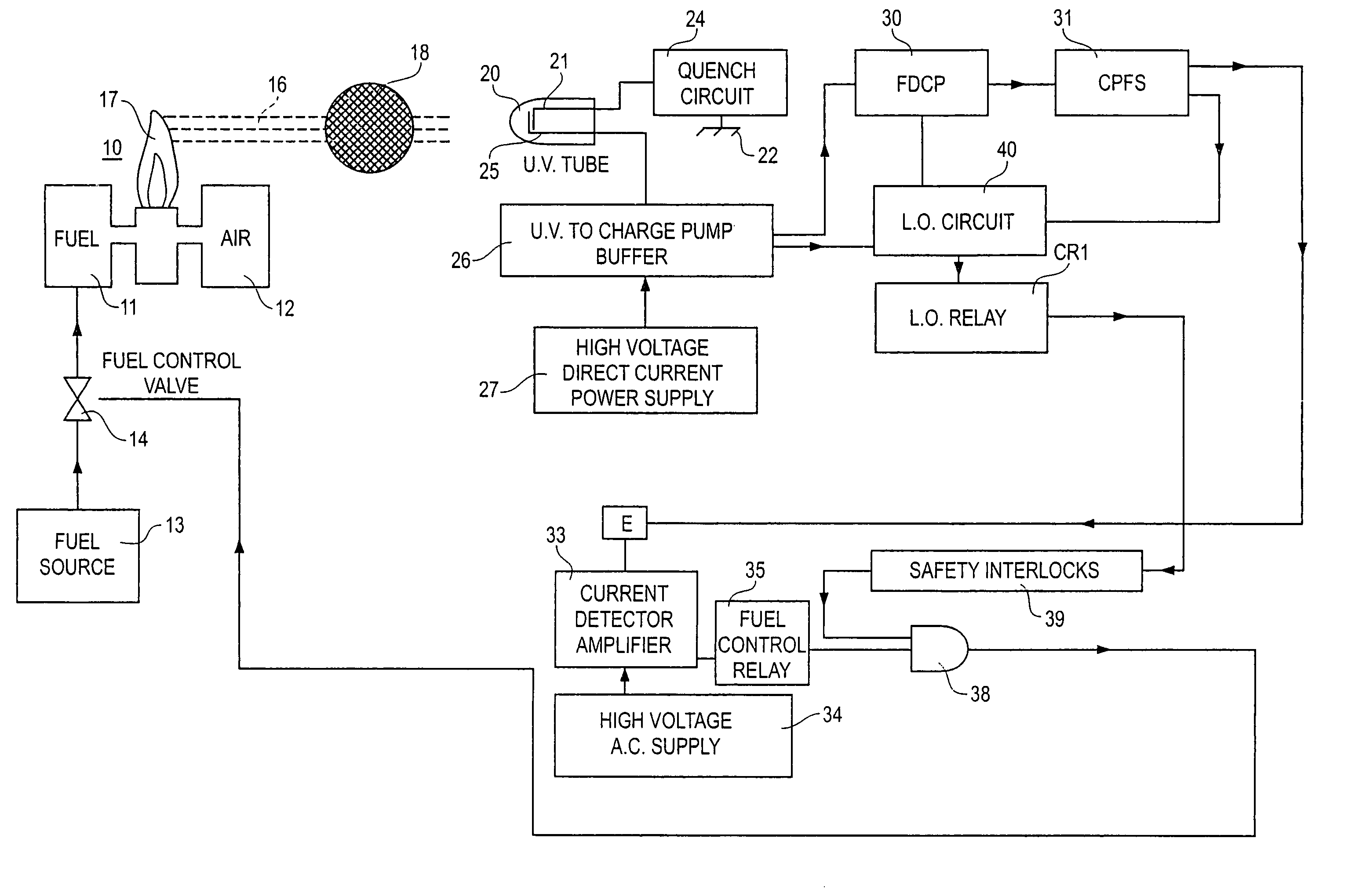
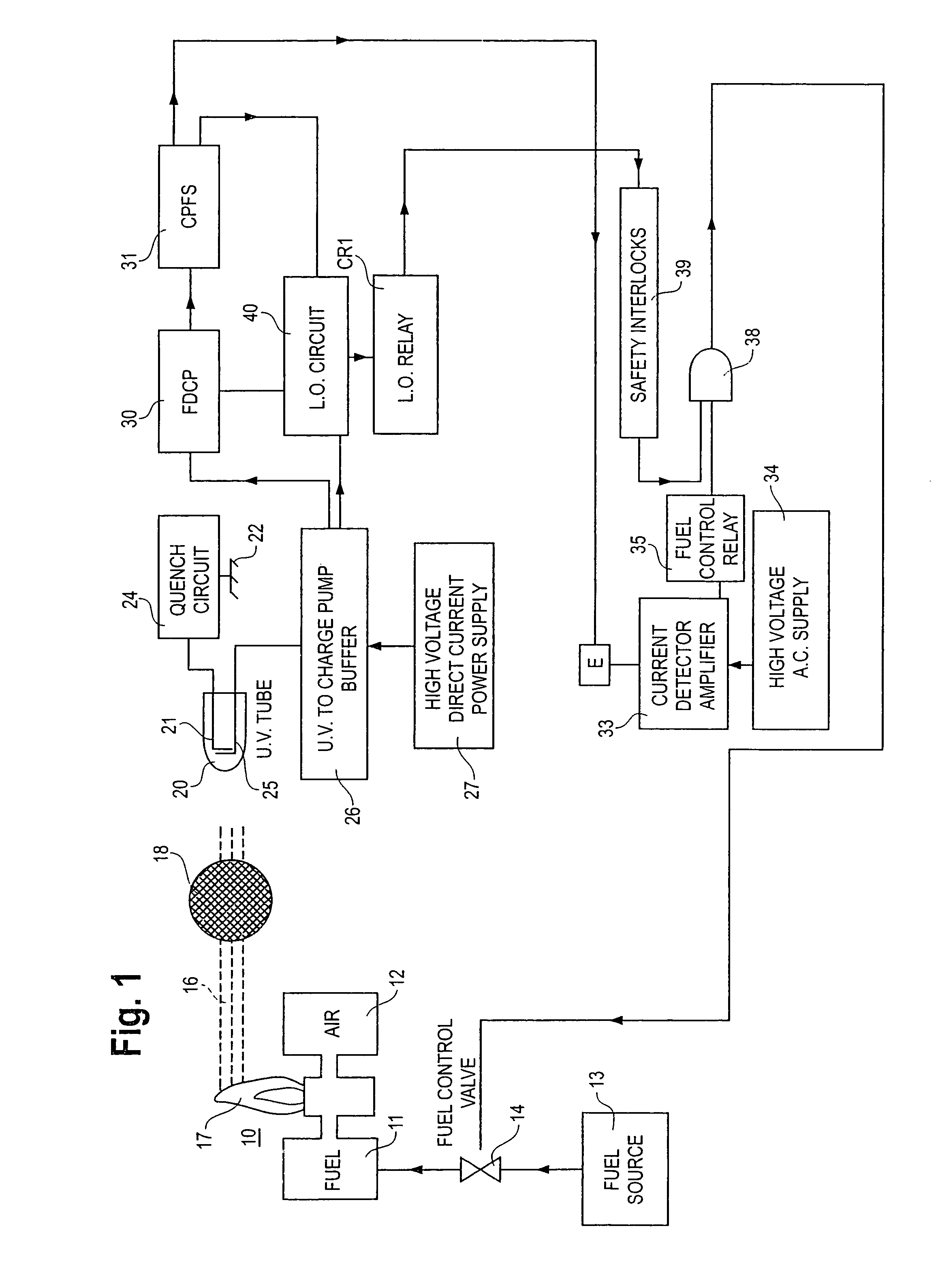
[0016]The basic operation of the flame detector and burner fuel valve control is illustrated in FIG. 1. A burner 10 has fuel and air inputs 11 and 12, respectively. A fuel source 13 is connected through a fuel control valve 14 with burner fuel input 11. UV radiation 16 from flame 17 is directed through an attenuating screen 18 to a UV sensor tube 20. No mechanical shutter is needed to interrupt the radiation periodically. The anode electrode 21 of the sensor tube is connected with a signal reference or ground 22 through quench circuit 24. Cathode electrode 25 is connected through a buffer circuit 26 with a high voltage direct, current power supply 27.
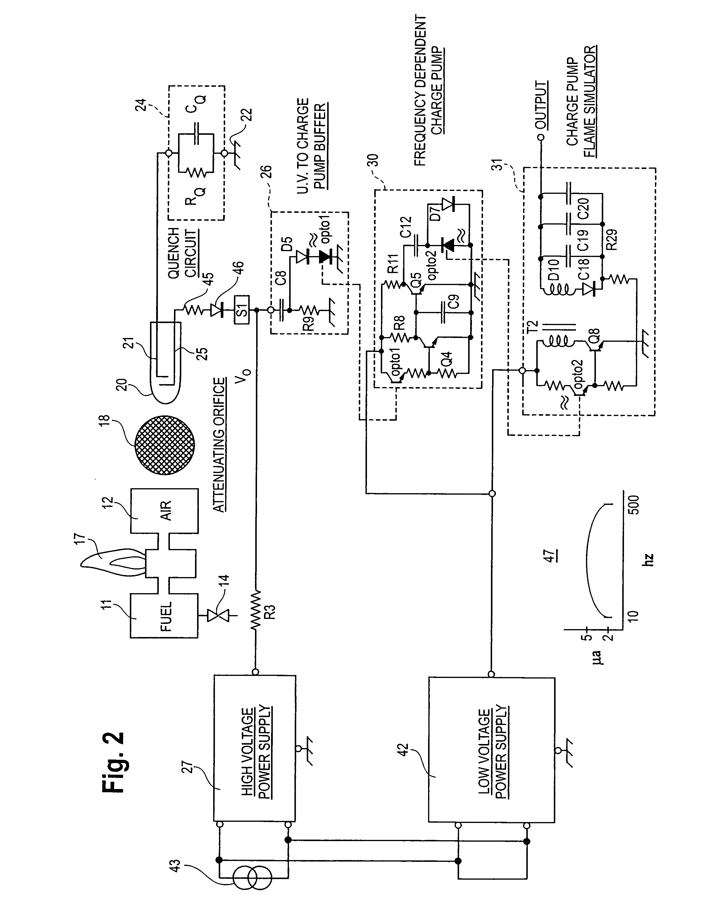
[0017]The repetition rate or frequency of the pulses in the sensor tube circuit is a function of the intensity of the UV radiation, the DC voltage applied to the tube and the time constant of quench circuit 24. The UV tube circuit may generate pulses at a low frequency as a result of electrical noise or cosmic rays, in the absence of UV...
PUM
 Abstract
Description
Claims
Application Information
 - R&D
- Intellectual Property
- Life Sciences
- Materials
- Tech Scout
- Unparalleled Data Quality
- Higher Quality Content
- 60% Fewer Hallucinations
Browse by: Latest US Patents, China's latest patents, Technical Efficacy Thesaurus, Application Domain, Technology Topic, Popular Technical Reports.
© 2025 PatSnap. All rights reserved.Legal|Privacy policy|Modern Slavery Act Transparency Statement|Sitemap|About US| Contact US: help@patsnap.com


