Compact spotting scope with side focus control

a compact, side focus technology, applied in the field of compact spotting scopes, can solve the problems of inability to focus on targets, limited operation focusing range, and inability to portability of most known spotting scopes, and achieve the effects of convenient hand-held use, small size and light weigh

Inactive Publication Date: 2006-08-08
LEUPOLD & STEVENS
View PDF16 Cites 39 Cited by
  • Summary
  • Abstract
  • Description
  • Claims
  • Application Information

AI Technical Summary

Benefits of technology

[0006]A compact spotting scope includes a housing supporting an optical system that defines a folded optical path within the housing. The optical system includes a movable optical element, which can be selectively displaced for adjusting an optical setting of the spotting scope, such as its focus. The spotting scope has a relatively light weight and small size to facilitate hand-held use. For example, a preferred embodiment weighs under 16 ounces (˜450 g) and measures less than about 8 inches (˜20 cm) long. Due to its relatively small size and weight, the compact spotting scope can be conveniently carried on a lanyard or other strap. It may also have a wider field of view and less magnification than a traditional spotting scope, to eliminate or reduce the need for a tripod or other steady support device. The housing is configured to fit in the palm of a user's hand and includes an outer surface having a grasping region positioned adjacent the folded optical path and sized so that the spotting scope can be held at eye level with one hand in an ergonomic arm and wrist position for steady support.
[0007]The spotting scope preferably includes a side-mounted adjustment knob operably coupled to the optical element for driving the optical element in response to rotation of the adjustment knob. The adjustment knob extends laterally from the outer surface of the housing opposite the grasping region and is sized so that the user can comfortably grasp and rotate the adjustment knob with his or her free hand. The side-mounted position of the adjustment knob allows the arm and wrist of the focusing hand to be maintained in an ergonomic position during manipulation of the adjustment knob, thereby further facilitating steady support of the spotting scope. The optical element may include an optical focusing element driven by the side-mounted adjustment knob for a variable rate of movement over the range of focus settings, by employing a mechanism such as the orbital drive pin of U.S. Pat. No. 4,643,542 of Gibson or the spiral cam of U.S. Pat. No. 6,351,907 of Otteman.
[0009]A preferred embodiment implements a novel internal support member for accurate alignment and compact support of critical optical components of the spotting scope. The support member includes a frame portion and a generally tubular portion, which are preferably integrally formed together of unitary molded construction. The tubular portion has a longitudinal axis and at least one guide feature extending along the longitudinal axis. The guide feature guides a power-varying optical element or set of optical elements slidably mounted within the tubular portion, restricting rotation of the power-varying optical element while allowing movement along the longitudinal axis. In a preferred embodiment, a cam sleeve of the eyepiece assembly is operably coupled to the power-varying optical element so that rotation of the eyepiece assembly causes the power-varying optical element to move along the longitudinal axis to adjust the optical power (magnification) of the compact spotting scope. In alternative embodiments, the optical elements driven by the eyepiece assembly adjust a different optical setting of the spotting scope, such as a focus setting.
[0010]The frame portion of the support member includes a seat that rigidly supports an optical beam directing element, such as a porro prism, at a precise position relative to the tubular portion and a precise angular orientation relative to the longitudinal axis of the tubular portion. A second optical beam directing element, such as a movable porro prism, is preferably mounted on a carriage that is slidably supported on a pair of guide pins press-fit into the support member. The guide pins ensure precise alignment of the second optical beam directing element relative to the tubular portion and the first optical beam directing element. The integral frame portion and tubular portion of the support member provide a shared platform for alignment of the first and second optical beam directing elements with other parts of the optical system, such as the power-varying optical element. These critical optical components can be pre-assembled on the support member in precise alignment and tested before installation into the housing, thereby improving the optical performance of the compact spotting scope. Advantageously, the frame portion of the support member, the guide pins, and the carriage may be contained entirely within the housing so that the optical beam directing elements are somewhat isolated from the housing to protect the optical beam directing elements from shock and external stresses.

Problems solved by technology

While it is often desirable to have the increased optical power of a spotting scope, the relatively large size and weight of most known spotting scopes inhibits portability.
Moreover, most known spotting scopes have a limited operational focusing range that does not allow a user to focus on targets located closer than 30 feet (9.1 meters).
A user rotates the jack screw knob by dragging a finger across the top of the knob or by reaching around the front of the knob to grasp it between the user's thumb and fingers—the latter motion being somewhat awkward.
However, the present inventors have found that at closer focusing distances the effect of such fine adjustments are more subtle, which can make it difficult to quickly visually assess the effect of adjustments and determine the direction in which the jack screw should be turned to achieve sharp focus.

Method used


Image

  • Compact spotting scope with side focus control
  • Compact spotting scope with side focus control
  • Compact spotting scope with side focus control

Examples


Embodiment Construction

[0023]Throughout the specification, reference to “one embodiment,” or “an embodiment,” or “some embodiments” means that a particular described feature, structure, or characteristic is included in at least one embodiment. Thus, appearances of the phrases “in one embodiment” or “in an embodiment” or “in some embodiments” in various places throughout the specification are not necessarily all referring to the same embodiment or embodiments.

[0024]Furthermore, the described features, structures, and characteristics may be combined in any suitable manner in one or more embodiments. Those skilled in the art will recognize that certain embodiments may be practiced without one or more of the specific details, or with other methods, components, materials and features. In other instances, well-known structures, materials, or operations are shown in simplified form or omitted to avoid obscuring aspects of the embodiments.

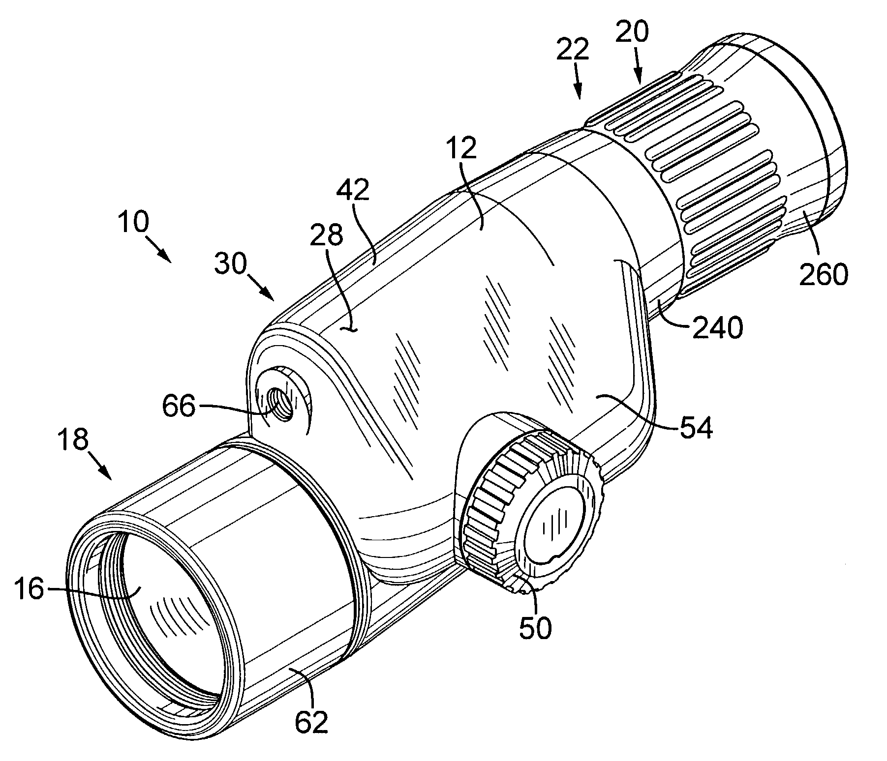
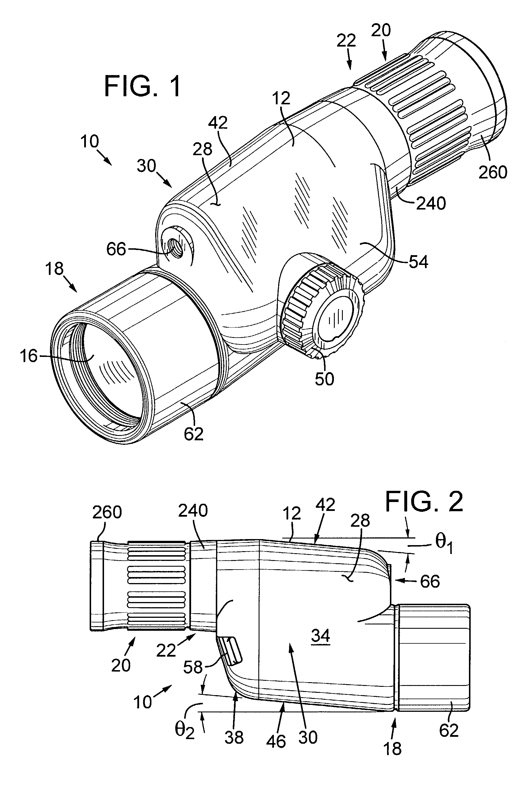
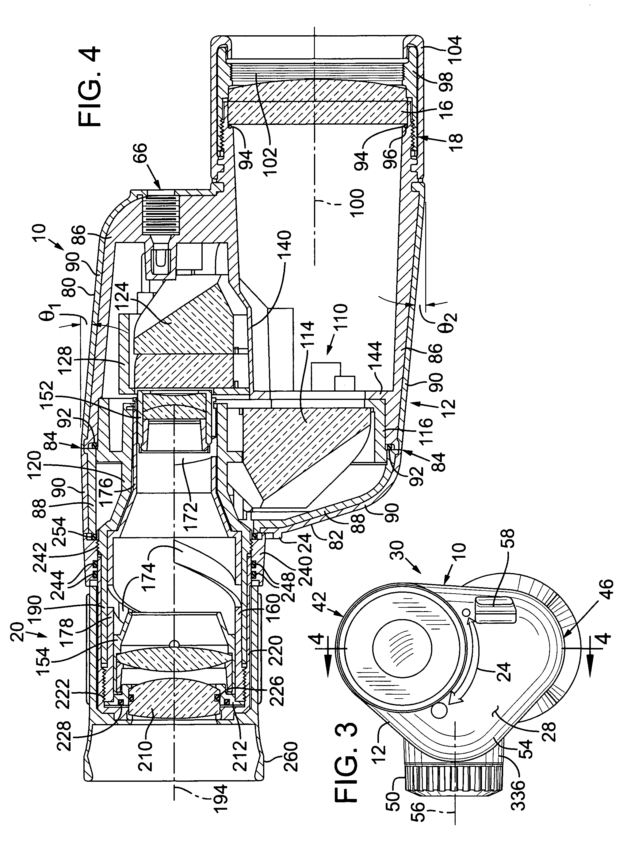
[0025]FIG. 1 is a pictorial view of a compact spotting scope 10 in accordan...


PUM


Abstract

A compact spotting scope includes a housing with an outer surface having a grasping region sized and shaped to fit in the palm of a user's hand so that the spotting scope can be held at eye level with one hand in an ergonomic arm and wrist position for steady support. An optical element positioned within the housing is adjusted by manually rotating a side-mounted adjustment knob that extends laterally from the outer surface of the housing opposite the grasping region. The side-mounted position of the adjustment knob allows the arm and wrist of the focusing hand to be maintained in an ergonomic position during manipulation of the adjustment knob, thereby further facilitating steady support. An internal support member of the spotting scope includes a frame portion and a generally tubular portion, which are preferably formed together of unitary one-piece construction for aligning optical elements of the spotting scope.

Description

RELATED APPLICATIONS[0001]U.S. patent application Ser. No. 29 / 180,735, filed Apr. 28, 2003, now U.S. Pat. No. D490,097, which is incorporated herein by reference.TECHNICAL FIELD[0002]The present invention relates to spotting scopes and, in particular, to a compact lightweight spotting scope having features to facilitate hand-held use.BACKGROUND OF THE INVENTION[0003]Spotting scopes are specialized optical telescopes used primarily for terrestrial observation, rather than astronomy, and which include a single optical path (monocular) and image-inverting optics. As compared to binoculars, spotting scopes typically have a higher optical power (usually magnifying between 12× and 60×), a narrower field of view, and a larger overall size and weight. While it is often desirable to have the increased optical power of a spotting scope, the relatively large size and weight of most known spotting scopes inhibits portability. The large size, relatively large mass, narrow field of view, and high...

Claims


Application Information

Patent Timeline
Patent Type & Authority Patents(United States)
IPC IPC(8): G02B23/00G02B7/04G02B23/02G02B23/16
CPCG02B7/04G02B23/16G02B23/02
Inventor REGAN, RICK R.OTTEMAN, RODNEY H.HALVERSON, ERIK R.
Owner LEUPOLD & STEVENS
Why Eureka
Try Eureka