
System and method for traffic shaping based on generalized congestion and flow control

a traffic shaping and generalized congestion technology, applied in the field of computer network communication, can solve problems such as inability to provide certainty of resource sharing, ineffective providing a traffic shaping mechanism, and incoming token overflow, and cannot be used for future packets

Active Publication Date: 2006-08-08
VL COLLECTIVE IP LLC
View PDF162 Cites 207 Cited by
  • Summary
  • Abstract
  • Description
  • Claims
  • Application Information

AI Technical Summary

Benefits of technology

[0014]In accordance with embodiments of the present invention, s

Problems solved by technology

The basic network parameters typically affecting network performance are bandwidth and delays since the application traffic between two network entities in a computer network may require a certain minimum bandwidth or may be sensitive to delays.
In general, the quality-of-service elements manage network resources according to application demands and network management settings and, thus, cannot provide certainty that resource sharing occurs.
However, equally important is that the high-priority applications do not disable low-priority Internet applications.
The leaky bucket implementation is typically employed for shaping traffic into flows with a fixed rate of admission into the network and is generally ineffective in providing a mechanism for shaping traffic into flows with variable rates of admission.
Similarly, if the bucket is full of tokens, incoming tokens overflow and are not available for future packets.
When RED is not configured, output buffers fill during periods of congestion.
As the congestion clears, the Transmission Control Protocol sources increase their data transmission rates, resulting in waves of congestion followed by periods where the transmission link is not fully used.
While the Random Early Detection mechanism and the variation thereof have been widely studied and employed in the existing computer networks, they suffer from a number of disadvantages.

Method used


Image

  • System and method for traffic shaping based on generalized congestion and flow control
  • System and method for traffic shaping based on generalized congestion and flow control
  • System and method for traffic shaping based on generalized congestion and flow control

Examples


Embodiment Construction

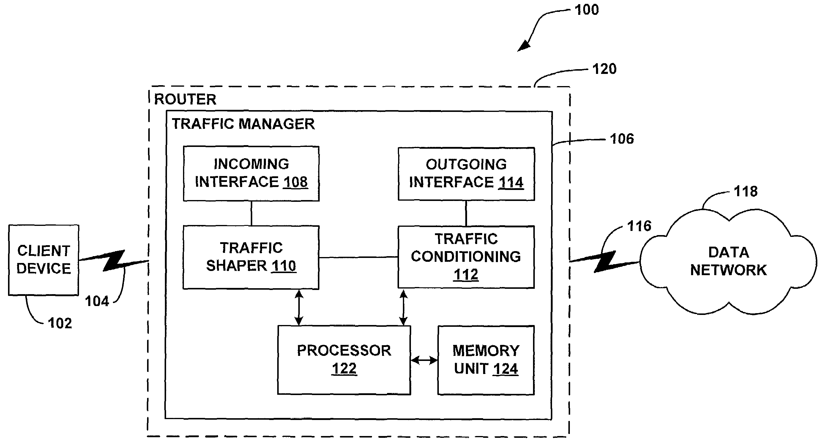
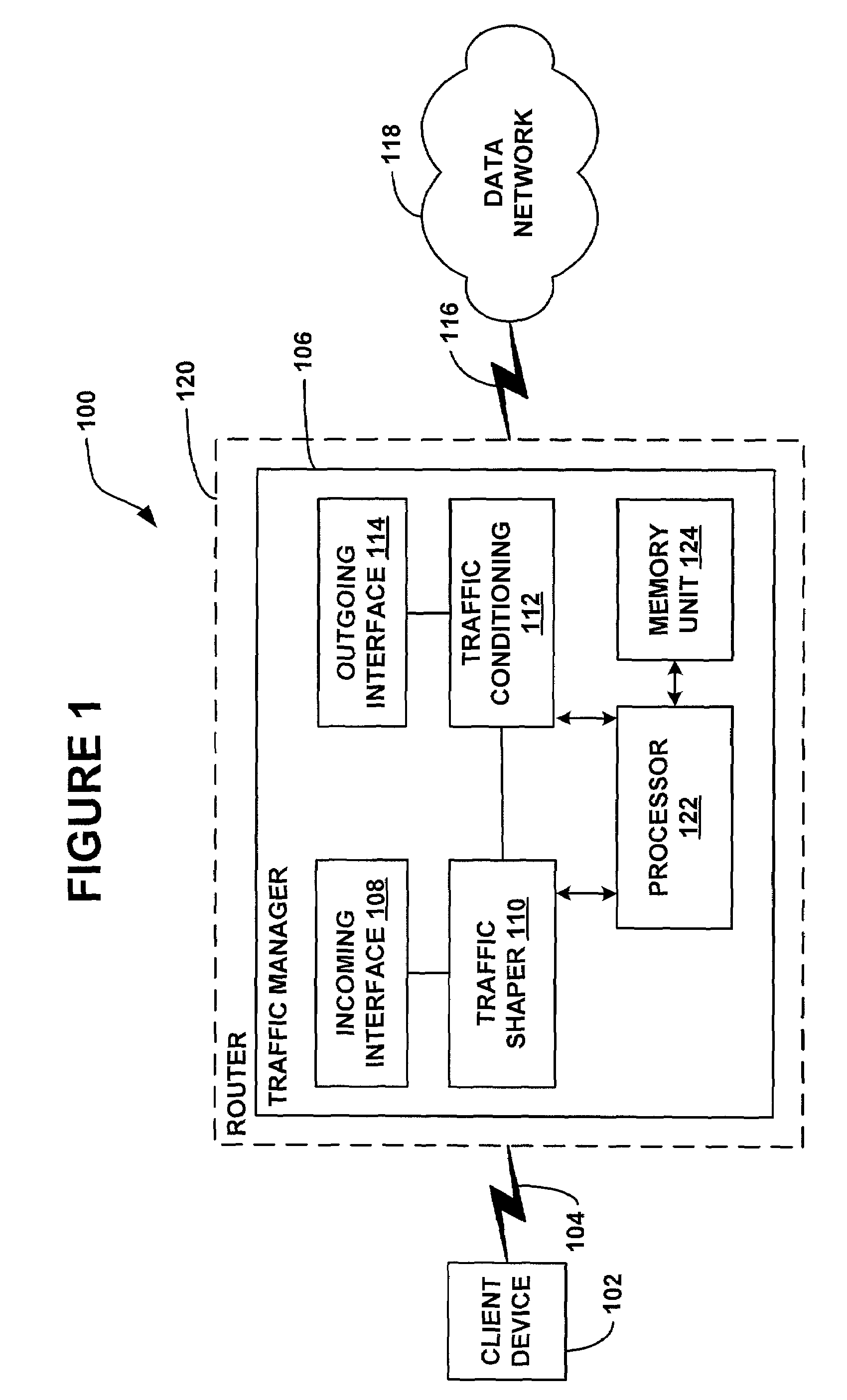
[0025]FIG. 1 is a functional block diagram illustrating an exemplary embodiment of a network architecture 100 suitable for application to the present invention for traffic shaping based on flow control and generalized congestion. FIG. 1 shows the architecture 100 including a data network 118, such as a public Internet Protocol (IP) network to which a router 120 is linked via a network connection 116. A user network entity, such as a client device 102, is linked to the router 120 via a communication link 104. The communication link 104, as will be described in greater detail below, may include a cable connection, a wireless connection, a dial-up connection, or any other network connection utilizing a network protocol including link-layer mechanisms for controlling data transmission from the client device 102.

[0026]In the network architecture 100 illustrated in FIG. 1, the router 120 may include an edge router. Edge routers typically assign IP priority to packets as the packets enter ...


PUM


Abstract

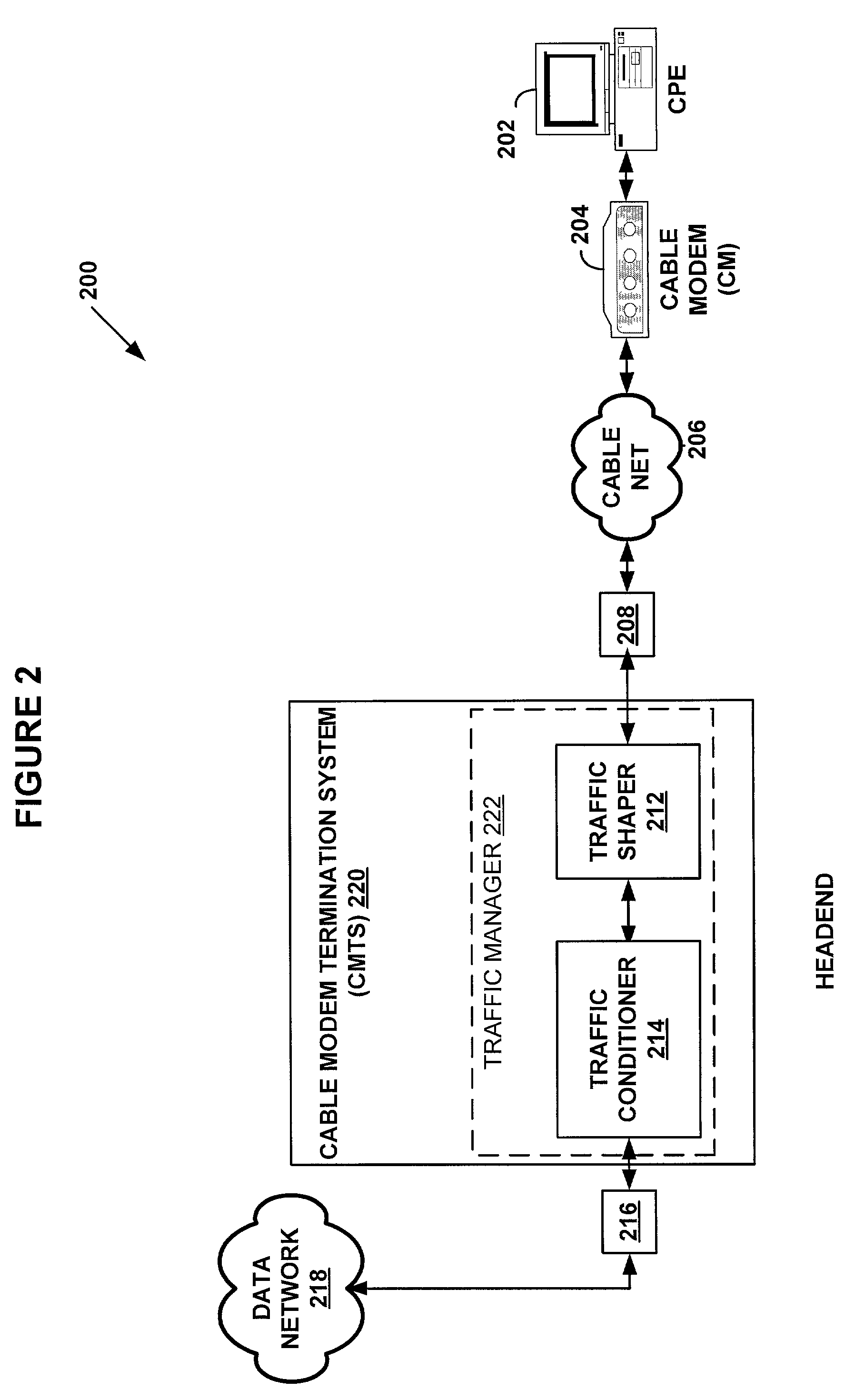
A system and methods are shown for traffic shaping and congestion avoidance in a computer network such as a data-over-cable network. A headend of the data-over-cable system includes a traffic shaper configured to calculate a packet arrival rate from a cable modem and a traffic conditioner configured to calculate an average queue size on an output interface to an external network. For example, the traffic shaper compares the packet arrival rate to three packet arrival thresholds including a committed rate threshold, a control rate threshold and a peak rate threshold. If the calculated packet arrival rate falls between the committed threshold and control rate threshold, the traffic shaper applies a link layer mechanism, such as a MAP bandwidth allocation mechanism, to lower the transmission rate from the cable modem.

Description

FIELD OF THE INVENTION[0001]The present invention relates to communications in computer networks. More specifically, it relates to a system and method for traffic shaping based on general congestion and flow control.BACKGROUND OF THE INVENTION[0002]In high-speed networks, routers are required to meet certain quality-of-service requirements associated with communicating network entities. As is known in the art, the quality-of-service is a communication network attribute that exists between two network entities requiring a predetermined network service level. The basic network parameters typically affecting network performance are bandwidth and delays since the application traffic between two network entities in a computer network may require a certain minimum bandwidth or may be sensitive to delays. Thus, in the simplest terms, the quality-of-service means providing consistent and predictable data delivery services to communicating network entities requiring a predetermined level of ...

Claims


Application Information

Patent Timeline
IPC IPC(8): H04L12/26
CPCH04L47/10
Inventor FREED, MICHAELAMARA, SATISHBORELLA, MICHAEL
Owner VL COLLECTIVE IP LLC
Learn More