Method for controlling a data stream in a wireless network

a wireless network and data stream technology, applied in the field of wireless personal area networks and wireless local area networks, to achieve the effect of increasing the data throughput speed of a wireless network and reducing the amount of dead tim

Inactive Publication Date: 2006-08-08
MOTOROLA INC +1
View PDF19 Cites 55 Cited by
  • Summary
  • Abstract
  • Description
  • Claims
  • Application Information

AI Technical Summary

Benefits of technology

[0022]An object of the present invention is to provide a method for increasing the data throughput speed for a wireless network.
[0023]Another object of the present in

Problems solved by technology

In addition, although FIG. 3 shows bi-directional lin

Method used


Image

  • Method for controlling a data stream in a wireless network
  • Method for controlling a data stream in a wireless network
  • Method for controlling a data stream in a wireless network

Examples


first preferred embodiment

[0110]As shown in FIG. 9, the transmission scheme 900 involves dividing the available transmission time into a plurality of superframes 910. This embodiment uses the MAC header 622 disclosed in FIG. 7A and the payloads 640 disclosed in FIGS. 8A through 8H.

[0111]In this embodiment each individual superframe 910 includes a beacon frame 920, an uplink MTS 930, a plurality of GTSs 940, and a downlink MTS 950.

[0112]The beacon frame 920 is a frame 600 whose payload 640 is a beacon payload 880, as shown in FIG. 8H. It indicates by association ID (known as a device ID in the IEEE 802.15.3 draft standard) a device 321–325 that is assigned to the current superframe 910. It also indicates via the RxTx table 888 [FIX THIS?] the transmitter / receiver pairs that are assigned to the individual GTSs 940.

[0113]In an alternate embodiment, a stream index may be added to allow multiple streaming between the same source-destination pair. This can be shown, for example, in the CTA for the draft 802.15.3 s...

second preferred embodiment

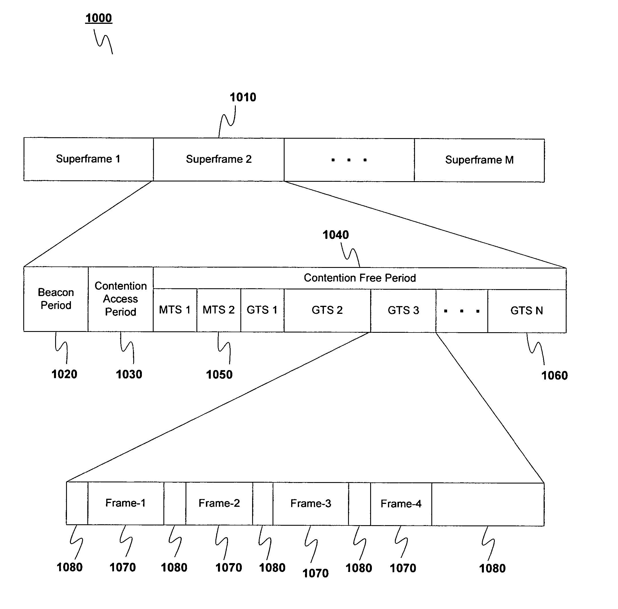
[0119]As shown in FIG. 10, the transmission scheme 1000 involves dividing the available transmission time into a plurality of superframes 1010. This embodiment uses the MAC header 624 disclosed in FIG. 7B. The payloads 640 used are preferably those used in the IEEE 802.15.3 standard.

[0120]In this embodiment the data transmission scheme 1000 includes transmitting successive superframes 1010 in time across the network 300. Each superframe 1010 includes a beacon 1020, an optional contention access period (CAP) 1030, and a contention free period (CFP) 1040. The contention free period 1040 may include one or more management time slots (MTSs) 1050 and one or more guaranteed time slots (GTSs) 1060.

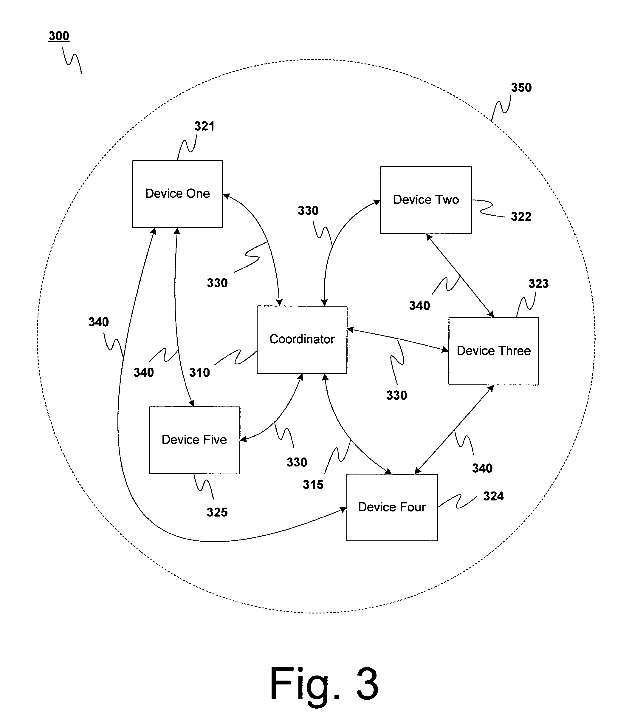
[0121]Management time slots 1050 can be downlink management time slots (DMTSs) in which information is sent from the coordinator 310 to a non-coordinator device 321–325, or uplink management time slots (UMTSs) in which information is sent from a non-coordinator device 321–325 to the coordinator 3...


PUM


Abstract

A method is provided for transmitting data packets from a source device in a wireless network. The source device receives a channel time allocation identifying the source device as assigned to transmit and a destination device as assigned to listen during the channel time allocation. If the source device has any primary data to send to the destination device, it will do so during the channel time allocation. If time remains in the channel time allocation once the primary data (if any) has been sent to the destination device, the source device will determine whether it has any secondary data to send to a secondary device. If so, the source device will determine whether the secondary device will be listening during the channel time allocation. If the secondary device will be listening, the source device then sends the secondary data to the secondary device during the channel time allocation.

Description

RELATED APPLICATION[0001]This application is a continuation-in-part of U.S. application Ser. No. 10 / 262,946, filed Oct. 3, 2002, entitled “METHOD OF OPERATING A MEDIA ACCESS CONTROLLER”, which benefits from the priority of a provisional application No. 60 / 326,425, filed Oct. 3, 2001, entitled “MiniMAC TDMA Protocol,” the disclosure of both of which are incorporated by reference in its entirety. This application also relies for priority on U.S. provisional application Ser. No. 60 / 416,520, by William M. Shvodian, filed Oct. 8, 2002, entitled “METHOD FOR CONTROLLING A DATA STREAM,” the contents of which are hereby incorporated by reference in their entirety.BACKGROUND OF THE INVENTION[0002]The present invention relates to wireless personal area networks and wireless local area networks. More particularly, the present invention relates to systems, methods, devices, and computer program products for controlling the transmission of data in a wireless personal area network or wireless loca...

Claims


Application Information

Patent Timeline
IPC IPC(8): H04Q7/20H04B7/00H04L12/28H04L12/56H04L29/08H04L29/12H04W28/06H04W84/18
CPCH04L29/12009H04L29/12018H04L61/10H04L69/324H04W28/06H04W84/18H04L61/00
Inventor SHVODIAN, WILLIAM M.
Owner MOTOROLA INC
Why Eureka
Try Eureka