Using an auxilary channel for video monitor training

a video monitor and auxilary technology, applied in the field of display devices, can solve the problems of sorely lacking in the ability to recognize and train a particular video monitor

Active Publication Date: 2006-08-08
GENESIS MICROCHIP
View PDF63 Cites 16 Cited by
  • Summary
  • Abstract
  • Description
  • Claims
  • Application Information

AI Technical Summary

Problems solved by technology

Unfortunately, however, the ability to recognize and

Method used


Image

  • Using an auxilary channel for video monitor training
  • Using an auxilary channel for video monitor training
  • Using an auxilary channel for video monitor training

Examples


Embodiment Construction

[0039]Reference will now be made in detail to a particular embodiment of the invention an example of which is illustrated in the accompanying drawings. While the invention will be described in conjunction with the particular embodiment, it will be understood that it is not intended to limit the invention to the described embodiment. To the contrary, it is intended to cover alternatives, modifications, and equivalents as may be included within the spirit and scope of the invention as defined by the appended claims.

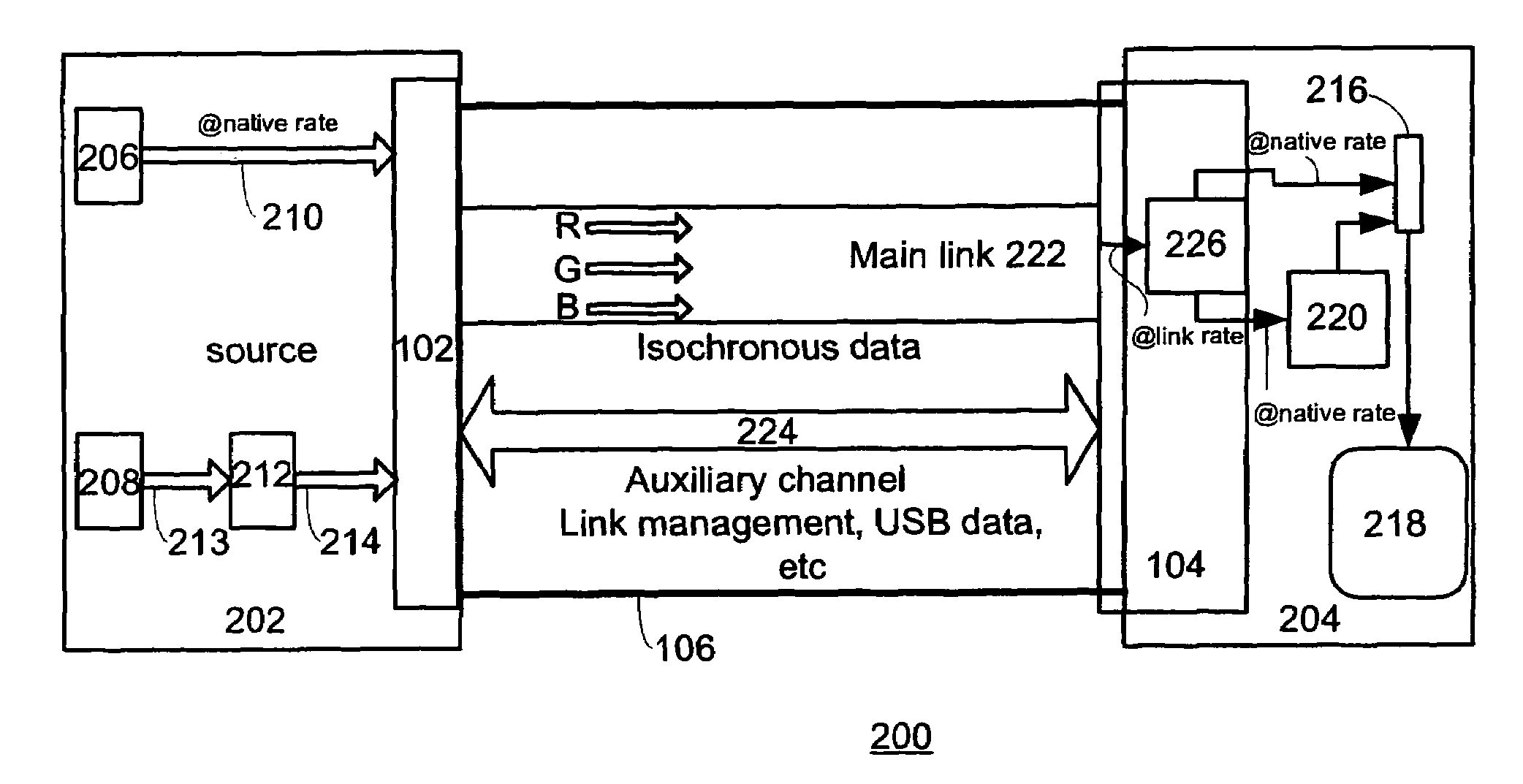
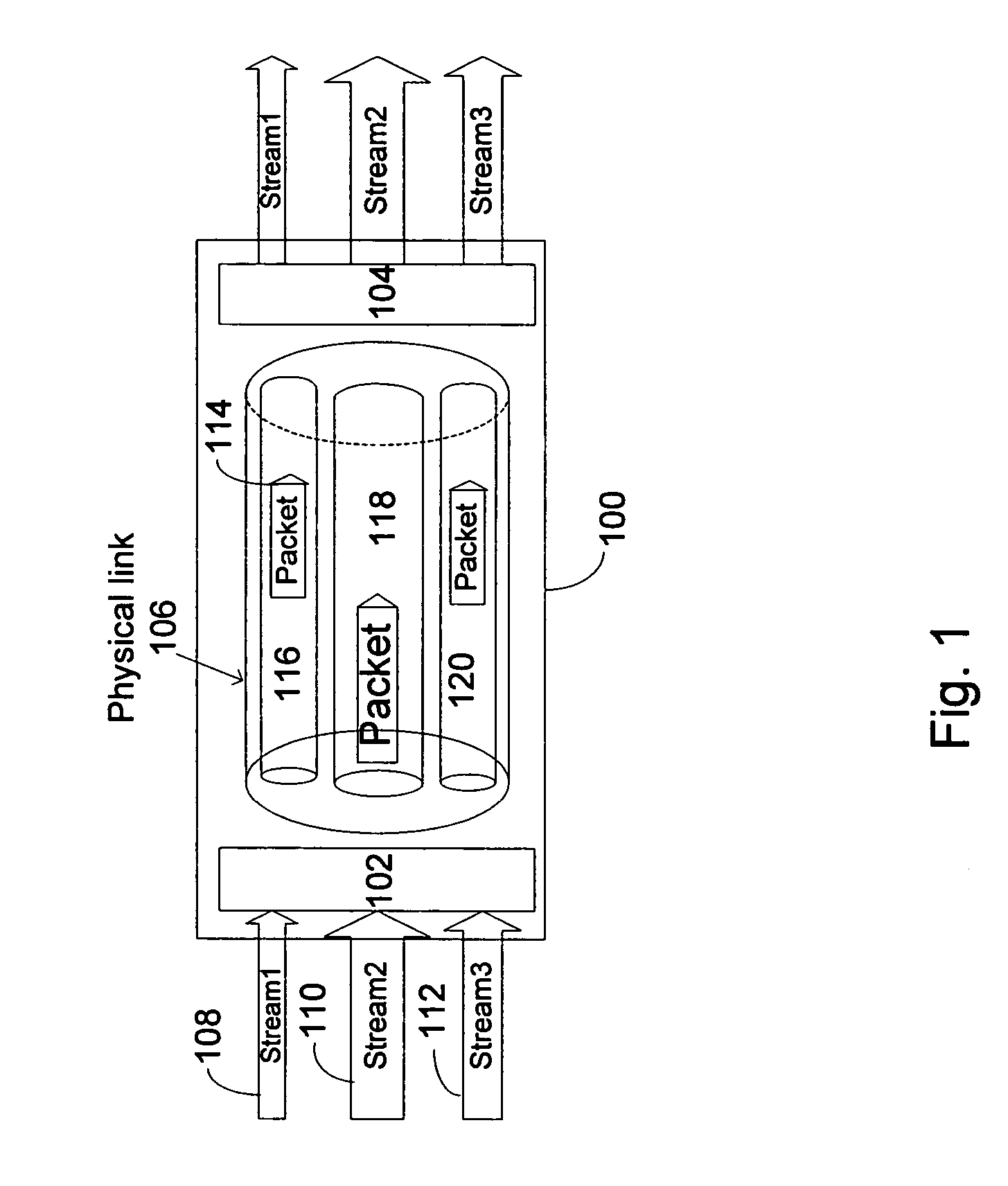
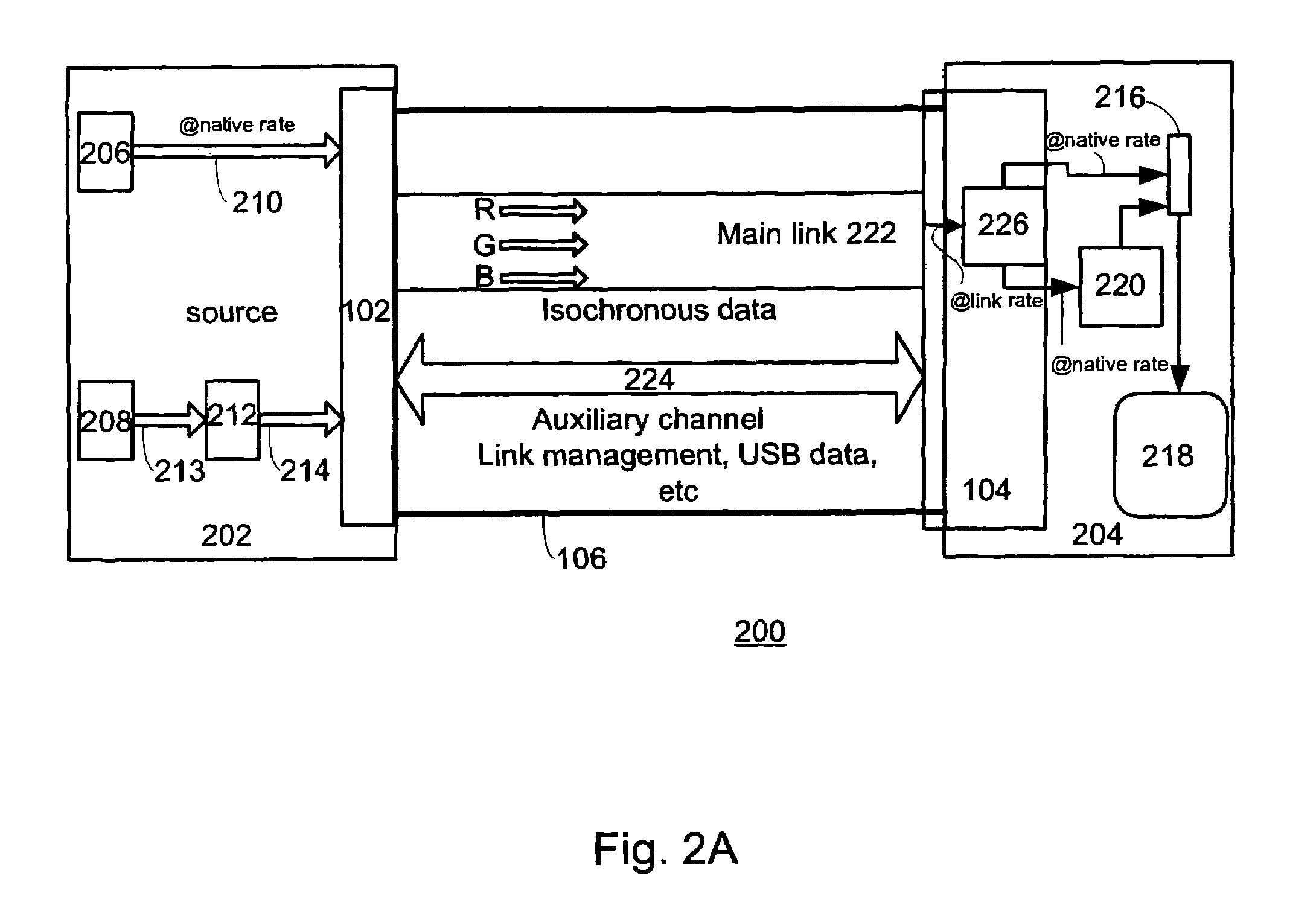
[0040]The inventive interface is a point-to-point, packet-based, plug & play, serial digital display interface that is both open and scalable that is suitable for use with, but not limited to, desktop monitors as well as providing LCD connectivity within notebook / all-in-one PC's, and consumer electronics display devices including HDTV displays and the like. Unlike conventional display interfaces that transmit a single video raster plus timing signals such as Vsync, Hsync, D...


PUM


Abstract

In a system having a bi-directional auxiliary channel arranged to transfer information between a video source and a video display and vice versa and a unidirectional main link arranged to carry a number multimedia data packets from the video source to the video display, a method of establishing a stable main link. The method is carried out by performing a link training session carried out over the auxiliary channel to establish the stable main link, prior to starting transmission of multimedia data packet streams from a video transmitter to a video receiver over the main channel.

Description

CROSS REFERENCE TO RELATED APPLICATION[0001]This patent application takes priority under 35 U.S.C. 119(e) to (i) U.S. Provisional Patent Application No.: 60 / 467,804, filed on May 1, 2003 entitled “DIGITAL / ANALOG VIDEO INTERCONNECT AND METHODS OF USE THEREOF” by Kobayashi, (ii) U.S. Provisional Patent Application No.: 60 / 504,060 filed on Sep. 18, 2003, entitled “DIGITAL / ANALOG VIDEO INTERCONNECT AND METHODS OF USE THEREOF” by Kobayashi, (iii) U.S. Provisional Patent Application No.: 60 / 474,085 filed on May 28, 2003, entitled “DIGITAL / ANALOG VIDEO INTERCONNECT AND METHODS OF USE THEREOF” by Kobayashi, and (iv) U.S. Provisional Patent Application No.: 60 / 474,084 filed on May 28, 2003, entitled “SIMPLE ENUMERATION METHOD FOR THE LINK CLOCK RATE AND THE PIXEL / AUDIO CLOCK RATE” by Kobayashi each of which are hereby incorporated by reference herein in their entirety. This application is also related to the following co-pending U.S. Patent applications, which are filed concurrently with thi...

Claims


Application Information

Patent Timeline
IPC IPC(8): H04J3/12G06F3/00G06F3/14G09G5/00H04J3/16H04L29/08H04N5/765H04N7/12H04N7/173
CPCG06F3/14G09G5/006G09G2370/047G09G2370/042H04N7/12
Inventor KOBAYASHI, OSAMU
Owner GENESIS MICROCHIP
Why Eureka
Try Eureka