
Combination tool

a technology of combinator and reaming blade, which is applied in the direction of boring/drilling equipment, reaming tools, turning equipment, etc., can solve the problem of inability to achieve a uniform angular pitch between the reaming blades, and achieve the effect of reducing the anti-penetration action and greater cutting for

Inactive Publication Date: 2006-08-15
KOMET GROUP GMBH
View PDF19 Cites 21 Cited by
  • Summary
  • Abstract
  • Description
  • Claims
  • Application Information

AI Technical Summary

Benefits of technology

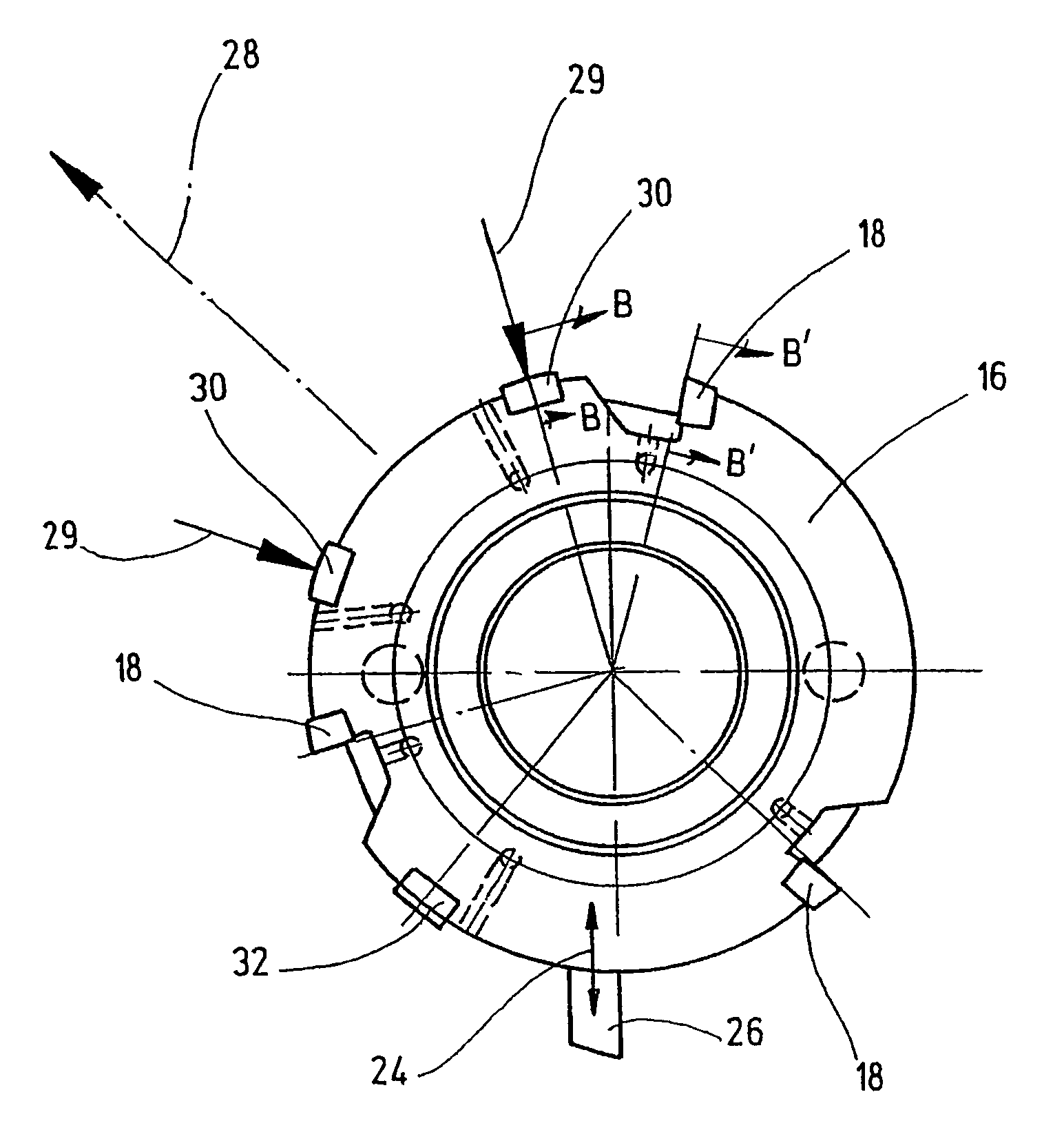
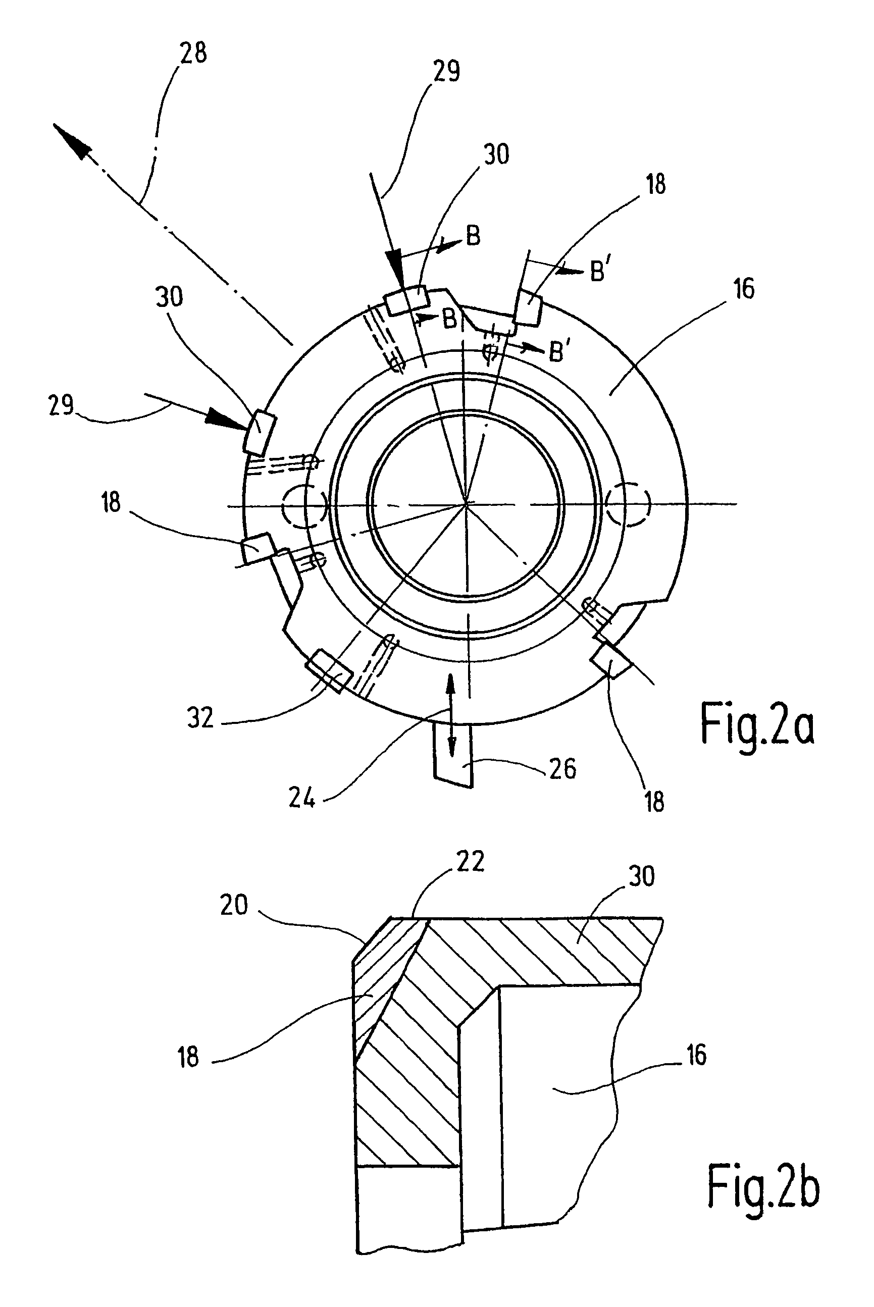
[0006]According to a preferred embodiment of the invention two simultaneously controllable grooving blades are provided, which are essentially diametrically opposite one another in the base body, and which have a common cutting-force resultant, which is position-stable in circumferential direction during the grooving operation. One of the two grooving blades can thereby function as a piercing blade or a roughing blade and the other one as a finishing grooving blade or a smoothing blade, whereby the roughing blade has always a greater cutting force than the smoothing blade. Such an arrangement results in a common cutting-force resultant, which is smaller than this is the case with only one grooving blade and thus brings about a reduction of the anti-penetration action.

Problems solved by technology

This can have the result that an equidistant angular pitch is not possible between the reaming blades.

Method used


Image

  • Combination tool
  • Combination tool
  • Combination tool

Examples


Embodiment Construction

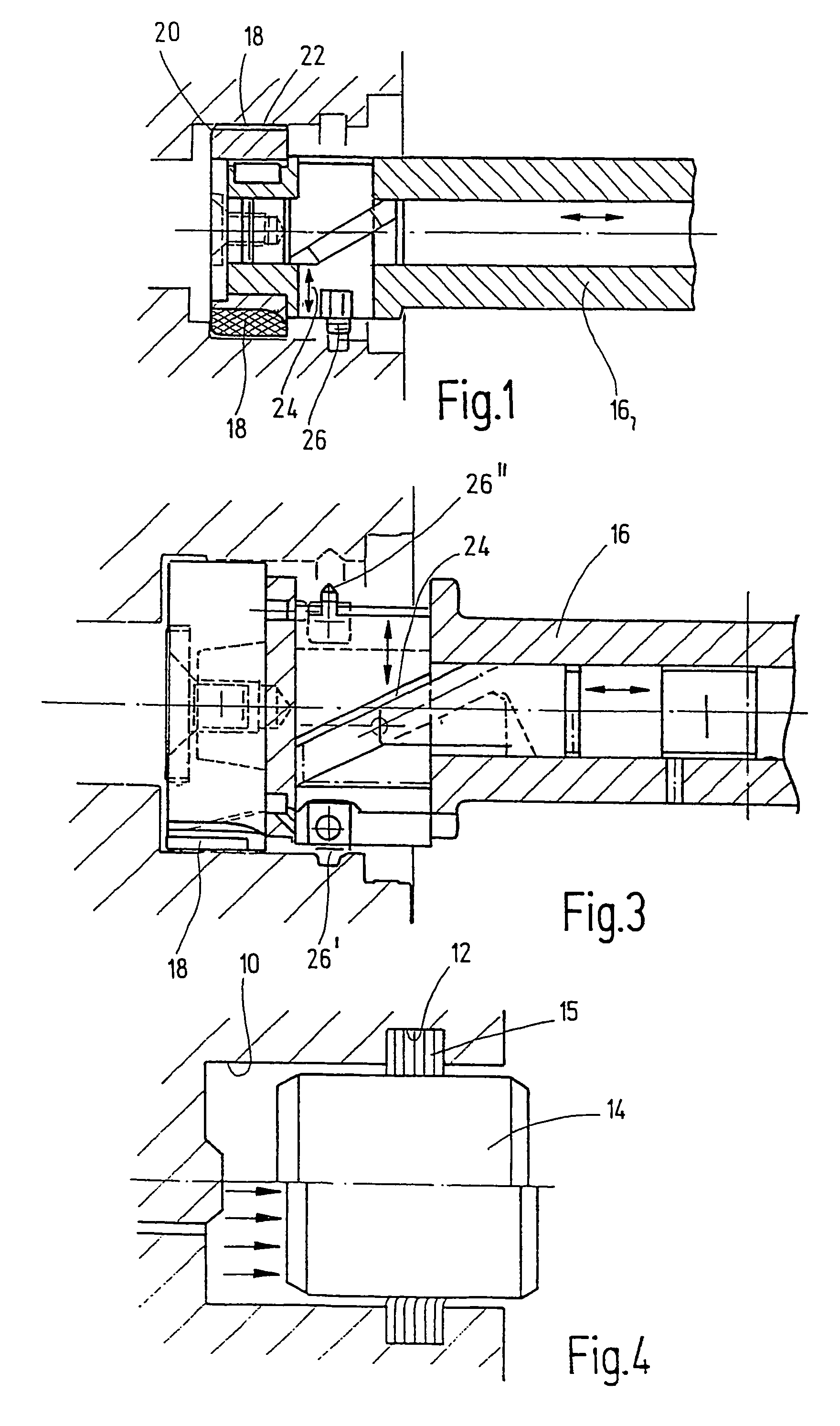
[0014]The combination tools illustrated in the drawings are designated for the reaming of cylinder bores 10 and for creating a radial enlargement 12 in the wall of the cylinder bore (FIG. 4). Bores of this type are used, for example, in the car industry in floating caliper disk brakes. The cylinder bore 10 is there designated to receive a piston 14, whereas the radial enlargement 12 is designated to receive a rubber packing ring 15 which bridges and pressure seals the annular space between the cylinder bore and piston. The piston 14 is illustrated in the resting state in the upper half of FIG. 4 and in the braking state in the lower half.

[0015]The combination tool has a base body 16, on the distal end of which are several reaming blades 18 distributively arranged over its circumference. The reaming blades 18 have each a chamfer 20 as the main blade and a guide surface 22 axially following said chamfer and defining the flight-circle radius. A grooving blade 26, which is radially mova...


PUM

PropertyMeasurementUnit
cutting-forceaaaaaaaaaa
circumferenceaaaaaaaaaa
angular distancesaaaaaaaaaa

Abstract

A combination tool including a base body with several reaming blades each having a chamfer and a guide surface, arranged around the circumference of the base body, for reaming a cylinder bore. The combination tool also has at least one grooving blade arranged axially offset from the reaming blades and which may be extended radially relative to the base body. The combination tool is provided with two guide strips, arranged in the base body, at an angle to each other, between two reaming blades which are adjacent in the circumferential direction and displaced axially relative to the above in the direction of the grooving blade.

Description

FIELD OF THE INVENTION[0001]The invention relates to a combination tool for use in machine tools for the machining of workpieces comprising a base body with several reaming blades for reaming a cylindrical bore, which reaming blades are distributively arranged over the circumference of the base body, and have a chamfer and a guide surface, and comprising at least one grooving blade arranged axially displaced with respect to the reaming blades and is radially movably controlled with respect to the base body.BACKGROUND OF THE INVENTION[0002]A combination tool of this type is known and has a high number, for example, ten, reaming blades distributively arranged over the circumference and a grooving blade radially movably controllable through a slide mechanism. The cutting forces occurring during the grooving operation are there received by the reaming blades supported in the bore. Due to the reaction forces occurring during the controlling of the grooving plates it is possible for the r...

Claims


Application Information

Patent Timeline
Patent Type & Authority Patents(United States)
IPC IPC(8): B23B29/34B23B29/034B23D77/00
CPCB23B29/03453B23D77/00B23D2277/46Y10T408/5586Y10T82/12Y10T408/909Y10T82/125Y10T408/8588
Inventor FEIL, ERICHMUECKSCHEL, KARL-HEINZ
Owner KOMET GROUP GMBH
Learn More