
Choke valve provided with an integrated electromagnetic actuator for an intake manifold with a retracting tumble system

a technology of electromagnetic actuator and choke valve, which is applied in the direction of air intake for fuel, engine components, engine controllers, etc., can solve the problems of reducing the maximum power that can be generated, reducing the maximum flow of air, and being more costly and complex to embody, so as to achieve easy and economic production

Inactive Publication Date: 2006-08-15
FAB ITAL MAGNETI MARELLI SPA
View PDF11 Cites 11 Cited by
  • Summary
  • Abstract
  • Description
  • Claims
  • Application Information

AI Technical Summary

Benefits of technology

[0006]The object of the present invention is to provide a choke valve for an intake manifold with a retracting tumble system, which is free from the drawbacks described above and which is, in particular, easy and economic to produce.

Problems solved by technology

This solution is simple and economic to embody, but the presence of the butterfly choke valves in the middle of the intake ducts entails high losses of load in the flow of air when the tumble system is not active because the profile of the butterfly valves is completely immersed in the air flow; obviously, these losses of load reduce the maximum flow of air that can be taken in by the cylinders, thereby reducing the maximum power that can be generated.
This solution enables better filling of the cylinders at high speeds, but is nevertheless more costly and complex to embody, as two independent intake ducts are provided for each cylinder; moreover, the generation of the turbulent movements at low speeds is not optimal as, for each cylinder, one of the two intake ducts has no variation of section.

Method used


Image

  • Choke valve provided with an integrated electromagnetic actuator for an intake manifold with a retracting tumble system
  • Choke valve provided with an integrated electromagnetic actuator for an intake manifold with a retracting tumble system
  • Choke valve provided with an integrated electromagnetic actuator for an intake manifold with a retracting tumble system

Examples


Embodiment Construction

[0013]Further scope of applicability of the present invention will become apparent from the detailed description given hereinafter. However, it should be understood that the detailed description and specific examples, while indicating preferred embodiments of the invention, are given by way of illustration only, since various changes and modifications within the spirit and scope of the invention will become apparent to those skilled in the art from this detailed description.

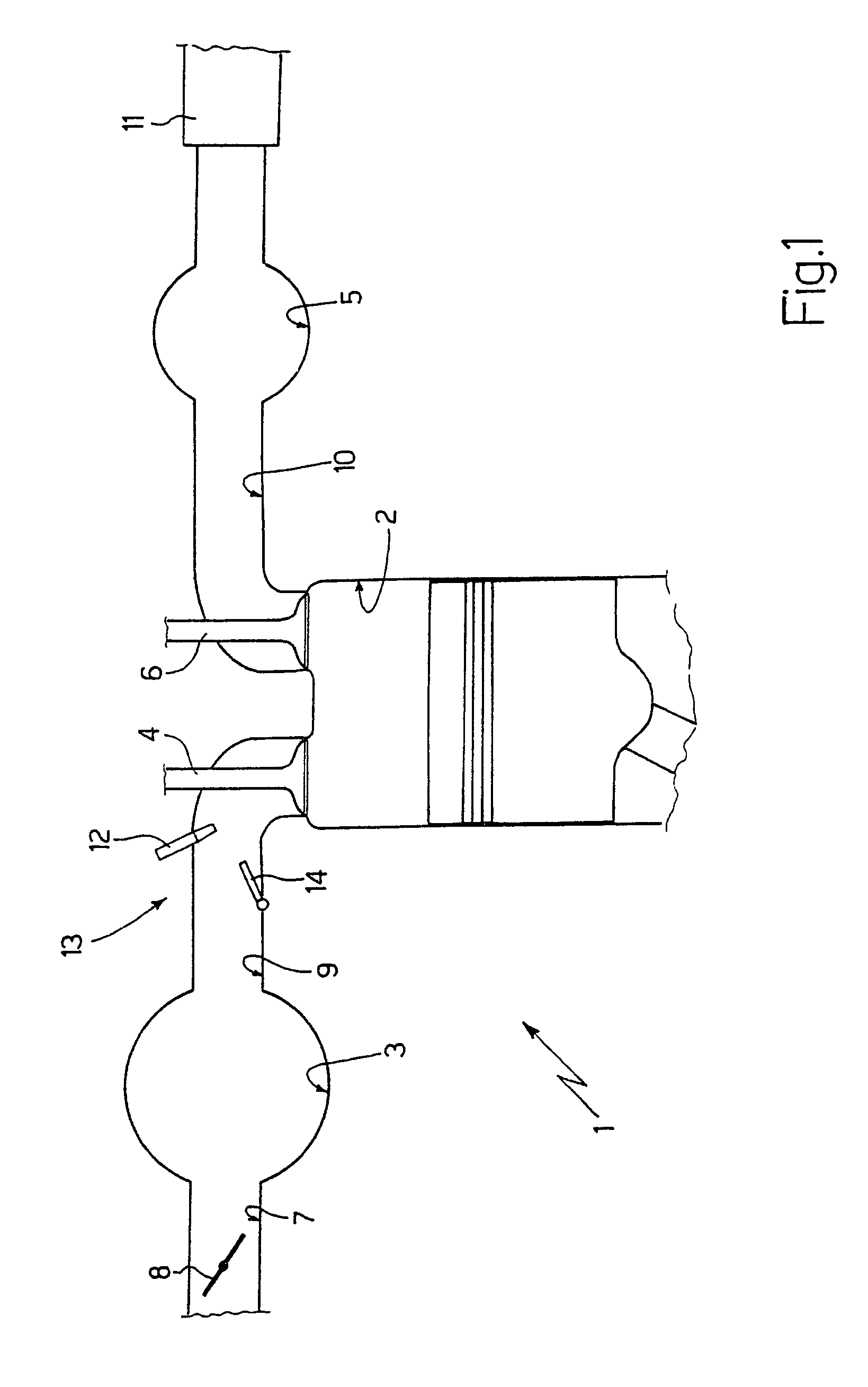
[0014]In FIG. 1, an internal combustion engine is shown overall by 1 and is provided with four cylinders 2 (only one of which is shown in FIG. 1), each of which is connected to an intake manifold 3 via a respective intake duct 4 and to an exhaust manifold 5 via a respective exhaust duct 6.

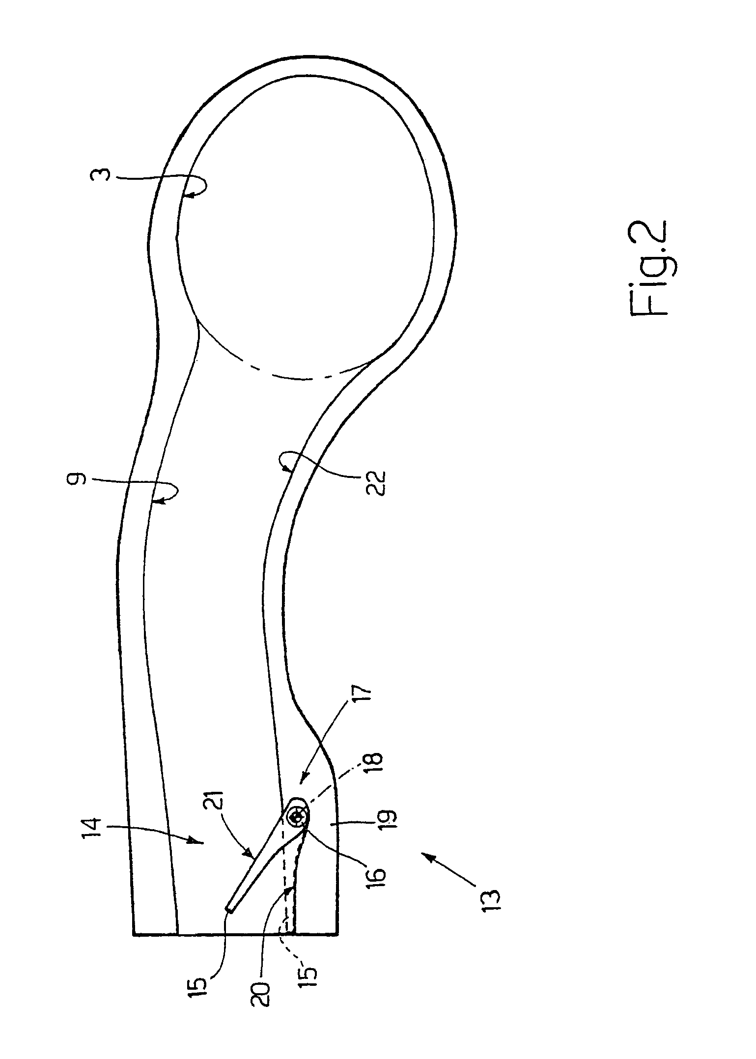
[0015]The intake manifold 3 receives fresh air (i.e. air from the external environment) via a supply duct 7 regulated by a butterfly valve 8 and is connected to the cylinders 2 by means of respective intake ducts 9 (only one of ...


PUM


Abstract

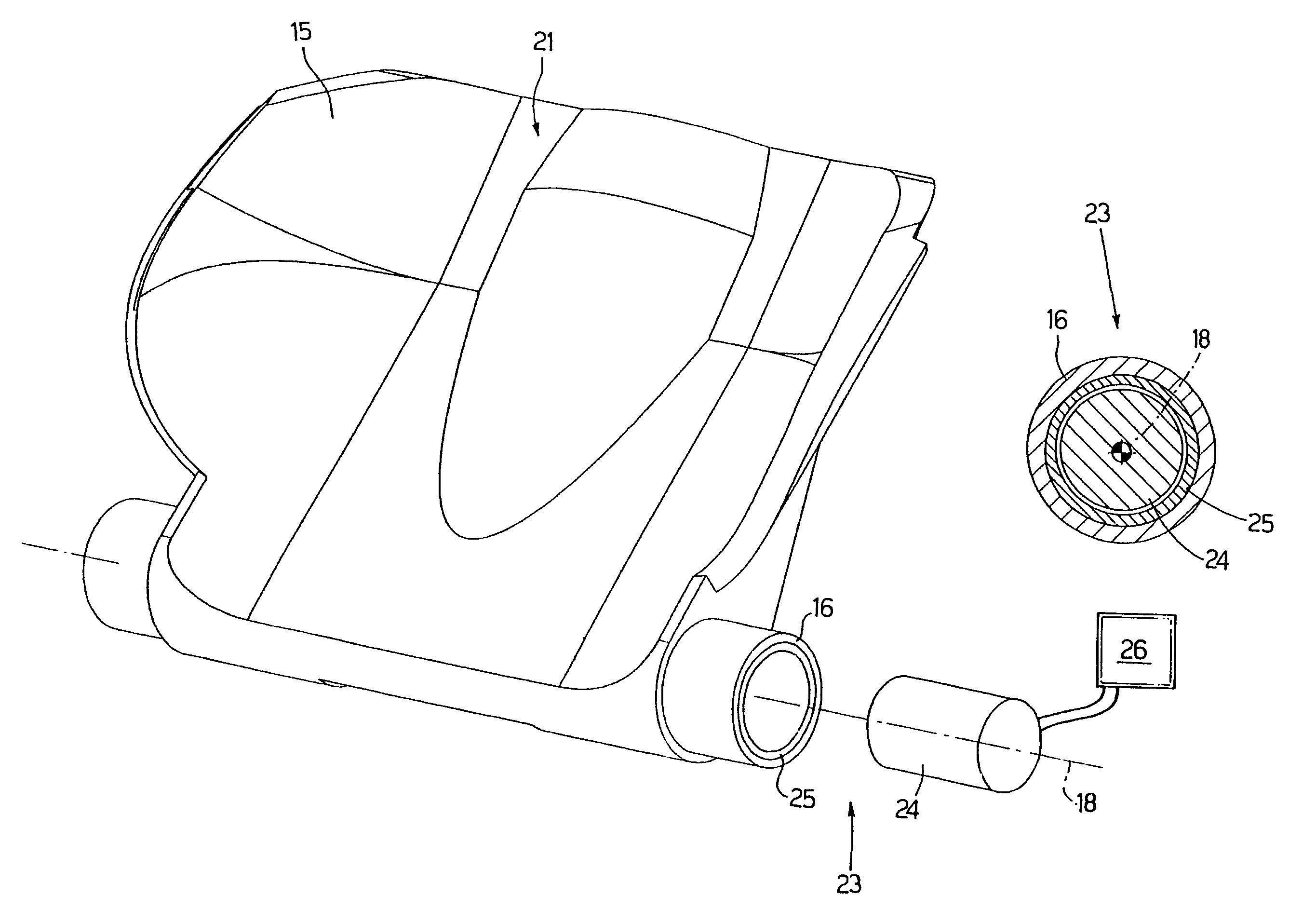
A choke valve for an intake manifold with a retracting tumble system for an engine provided with a number of cylinders, the choke valve being adapted to vary the passage section of the air through an intake duct which connects each cylinder with the intake manifold and is regulated by at least one intake valve; the choke valve comprises a butterfly mounted to rotate about an axis of rotation disposed transversely and externally with respect to the corresponding intake duct under the thrust of a corresponding rotary electric motor which comprises a stator and a rotor housed directly in the butterfly.

Description

[0001]The present invention relates to a choke valve for an intake manifold with a retracting tumble system.BACKGROUND OF THE INVENTION[0002]An internal combustion engine is provided with a number of cylinders, each of which is connected to an intake manifold by means of a respective intake valve and to an exhaust manifold valve by means of a respective exhaust valve. The intake manifold receives fresh air (i.e. air from the external environment) via a supply duct regulated by a butterfly valve and is connected to the cylinders by means of respective intake ducts, each of which is regulated by a corresponding intake valve.[0003]It has recently been proposed to introduce a tumble system which is adapted to vary, during operation of the engine, the section of the intake ducts as a function of the engine speed (i.e. the angular speed of rotation of the drive shaft). At low speeds, the passage section of the air through the intake ducts is decreased in order to generate turbulent moveme...

Claims


Application Information

Patent Timeline
Patent Type & Authority Patents(United States)
IPC IPC(8): F02B31/00F02B31/08F02B31/06F02D9/10
CPCF02B31/06F02D9/103Y02T10/146Y02T10/12
Inventor MOSCHINI, RENZOBELLATO, NAZARIOLANCIONI, FEDERICONAZZARO, RICCARDOSIRANI, SANDRO
Owner FAB ITAL MAGNETI MARELLI SPA
Learn More