Magazine strip

a technology for magazine strips and drive-in tools, which is applied in the field of magazine strips, can solve the problems of increasing the manufacturing cost of drive-in tools, increasing the manufacturing cost of magazine strips, and complex cross-sections of magazine strips, and achieves low manufacturing costs, good transition, and cost-effective effects

Active Publication Date: 2006-08-15
HILTI AG
View PDF6 Cites 8 Cited by
  • Summary
  • Abstract
  • Description
  • Claims
  • Application Information

AI Technical Summary

Benefits of technology

[0011]With such receptacles, the magazine strip has a simple shape with e.g., a substantially rectangular flat cross-section. Correspondingly, the receiving cross-section of the drive-in tool and the magazine receptacle can also be formed relatively simple. In addition, fastening elements, which are retained in the inventive magazine strip, can be relatively easy released. As a result, the manufacturing costs are reduced, and a disturbance-free operation of the magazine strip is insured.
[0012]Advantageously, each receptacle is provided with at least one stop element formed on at least one of the lower an upper surfaces. All of the stop elements are arranged one after another in a longitudinal direction of support strap. Such stop elements provide for a precise positioning and alignment of a fastening element in the magazine strip. According to the invention, the stop elements, which have the same cross-section are arranged in the longitudinal direction within a common projection course. This insures a cost-effective manufacturing of a magazine strip itself and of the drive-in tool and the magazine receptacle.
[0013]According to a preferred embodiment of the present invention, the stop elements are formed by sections of a through-rib formed over a length of the support strap. The through-rib is interrupted over the axial lengths of respective receptacles. The stop elements increase a contact region between fastening elements and the magazine strip, as there are provided, at the edge of each receptacle, two end surfaces formed by adjacent sections of the through-rib which project upwardly from the support strap. The larger contact surface insures a stable, frictional retention of a fastening element in the magazine strip. At that, these stop elements can be precisely and cost-effectively produced.
[0015]The method of manufacturing an inventive magazine strip includes forming, in the first step, the support strap together with a through-rib provided on at least one of lower and upper surfaces of the support strap, and includes forming, in a second step, the receptacles by stamping through the through-rib. This method is very cost-effective and insures a particular good transition from edge surfaces of the receptacles to opposite end surfaces of adjacent stop elements.
[0016]It is particularly advantageous when the first step is effective by extrusion, which insures production of magazine strip with particularly low manufacturing costs.

Problems solved by technology

The need to form the bearing walls and the stop ribs substantially increases manufacturing costs of the magazine strip.
Moreover, the projecting from the strip bottom, bearing walls and the stop ribs make the cross-section of the magazine strip rather complex.
The complex cross-section of the magazine. strip necessitates forming of rather complex receiving cross-sections of the drive-in tool and of the magazine receptacle.
This, in turn, increases manufacturing costs of a drive-in tool and makes it more prone to malfunction.

Method used


Image

  • Magazine strip
  • Magazine strip
  • Magazine strip

Examples


Embodiment Construction

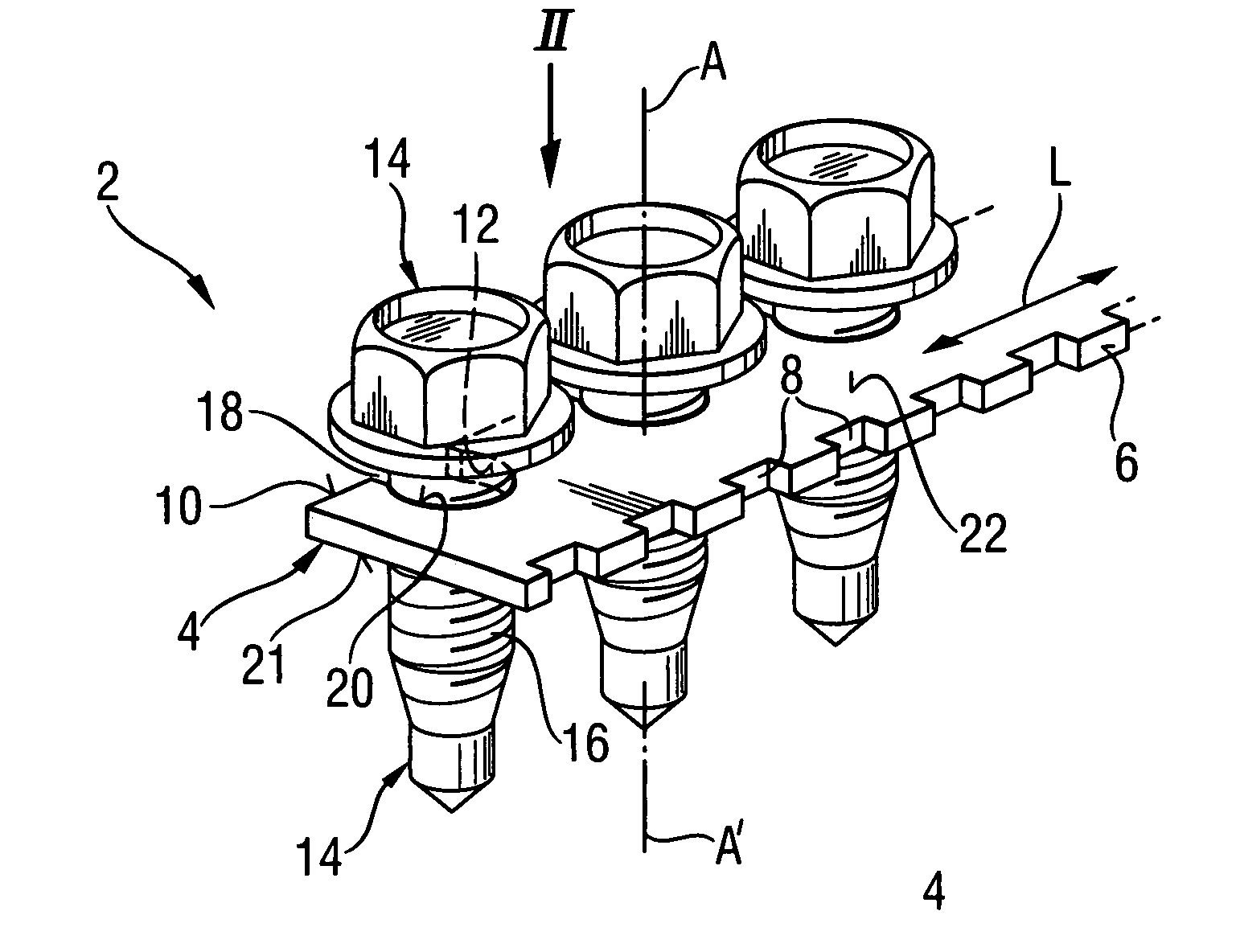
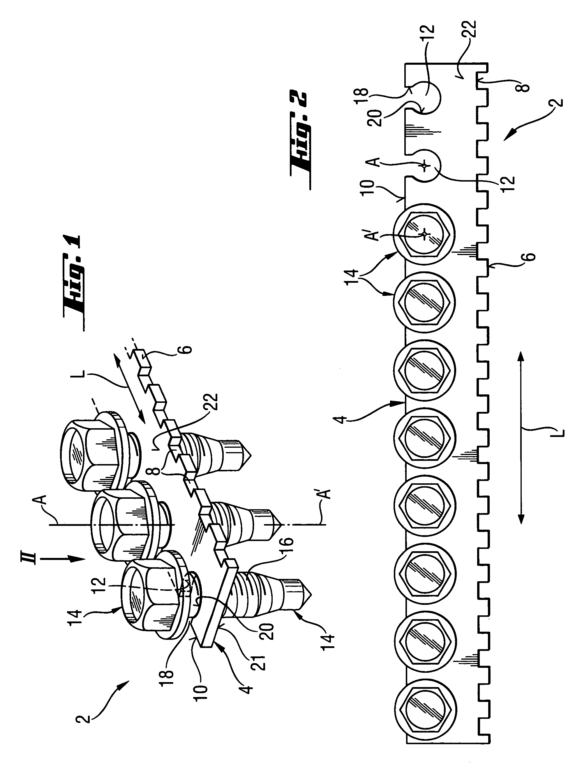
[0023]A magazine strip 2 according to the present invention, which is shown in FIGS. 1–2, consists essentially of a strip-shaped support strap 4. The support strip 4 has a first longitudinal edge 6 which is provided with uniformly spaced from each other, transporting recesses 8 in form of pockets. The second, opposite longitudinal edge 10 is provided with a plurality of uniformly spaced from each other, cylindrical receptacles 12 having each an axis A, in which fastening elements 14 such as, e.g., screws, bolts, or nails are received, with their stems 16 retained in respective receptacles 12. The receptacle 12 are opened at the second. longitudinal edge 10 with their respective opening 18, as it is particularly shown in FIG. 2.

[0024]The transporting recesses 8 are engageable with a transporting device that automatically transports stepwise the magazine strip 2 in a magazine receptacle to place fastening elements 14 one after another along a drive-in axis of a respective drive-in too...


PUM


Abstract

A magazine strip (2) for fastening elements (14) includes a strip-shaped support strap (4), a plurality of uniformly spaced from each other, transporting recesses (8) for a stepwise displacement of the magazine strip (2) in a magazine receptacle and opening toward a first one (6) of opposite longitudinal edges of the strap, and a plurality of substantially cylindrical receptacles (12) for retaining fastening elements (14) and limited by a lower surface (21) and an upper surface (22) of the support strap (4) and opening toward a second one (10) of the opposite longitudinal edges of the support strap (4).

Description

BACKGROUND OF THE INVENTION[0001]1. Field of the Invention[0002]The present invention relates to a magazine strip for fastening elements, such as, in particular, screws, having a strip-shaped support strap with a flat cross-section, a plurality of uniformly spaced from each other transporting recesses for a stepwise displacement of the magazine strip in a magazine receptacle, and a plurality of substantially cylindrical receptacles for retaining fastening elements which extend through the support strap. The present invention also relates to a method of manufacturing of the inventive magazine strip.[0003]2. Description of the Prior Art[0004]Magazine strips of the type described above are used in driving-in tools such as, e.g., screw driving or nail-driving tools, in which fastening elements are automatically displaced one after another into a position in which they are arranged coaxially with the drive-in axis along which the fastening elements are driven in a work-piece. Forming a m...

Claims


Application Information

Patent Timeline
Patent Type & Authority Patents(United States)
IPC IPC(8): B65D85/24F16B27/00
CPCF16B27/00
Inventor PALLY, ANDREASDAUBINGER, GERD
Owner HILTI AG
Why Eureka
Try Eureka