Energy absorbing support for vehicular passengers

a technology for vehicular passengers and support rods, applied in the field of seat cushions, can solve the problems of causing whiplash injury, unable to clearly demonstrate the benefits of good head restraint positioning, and certain faulty premises remain

Inactive Publication Date: 2006-08-15
DELLANNO RONALD P
View PDF16 Cites 36 Cited by
  • Summary
  • Abstract
  • Description
  • Claims
  • Application Information

AI Technical Summary

Problems solved by technology

However, in an accident analysis study conducted by the Transport Research Laboratory, Berkshire, United Kingdom, and the University of Manchester, Hope Hospital, Manchester, United Kingdom, the benefits of good head restraint positioning could not be clearly demonstrated.
Certain faulty premises continue to exist regarding rear-end, low-speed collisions.
One of these is that whiplash injury is caused by a typical hyperextension movement of the head and neck.
This results in an abnormal double harmonic curve in the cervical spine often referred to as the dreaded “S” curve.
This was accomplished with cineradiography, which showed significant aberration in motion during rear-end impact, resulting in facet plate collision and impingement.
Such materials while they may absorb some of the impact energy which is generated as the passenger is thrown rearwardly against the seat during a rear end impact, promptly transfer the absorbed energy back to the passenger, causing a rebound effect, which only adds to the detrimental conditions which foster injury.
In addition to being injured, this flattening of the thoracic spine causes axial loading into the cervical spine as the weight of the head and upward pressure of the flattening thoracic spine serve as end point forces to damage the cervical spine.

Method used


Image

  • Energy absorbing support for vehicular passengers
  • Energy absorbing support for vehicular passengers
  • Energy absorbing support for vehicular passengers

Examples


Embodiment Construction

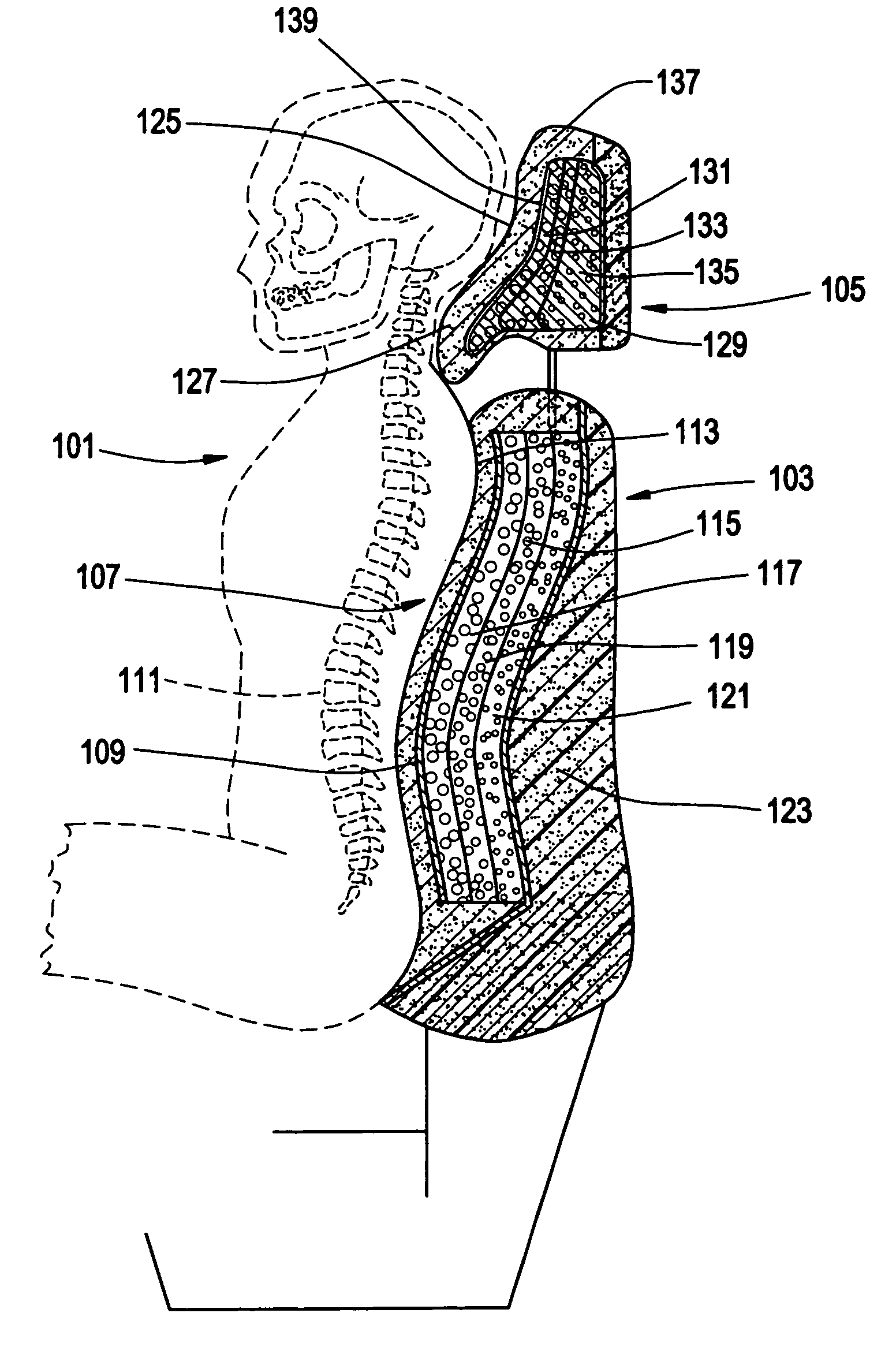
[0047]In FIG. 3 a schematic cross-sectional view appears depicting a passenger 101 seated in a vehicle in which the passenger is rearwardly supported by a seat back generally designated at 103 and a head-neck restraint 105, each being in accordance with the present invention. Seat back 103 thus incorporates a thoracic-lumbar restraint 107 which includes a rigid plate 109, e.g. of a rigid plastic or metal, having a shape which substantially conforms to the thoracic-lumbar spinal portion 111 of passenger 101. Plate 109 is overlaid by a conventional comfort material 113 such as a soft foam or covered upholstery layer or the like against which the passenger actually rests. Directly behind plate 109 is an energy aborbing zone 115 consisting of a series of overlying layers 117, 119 and 121. In general terms these energy absorbing layers function in the manner disclosed in my aforementioned U.S. Pat. No. 5,580,124; i.e. upon a rear impact at the vehicle in which passenger 101 is seated, th...


PUM


Abstract

Apparatus for preventing or limiting spinal injuries to a passenger seated in a forward facing position in a moving vehicle during vehicular impact or sudden deceleration. The apparatus includes a vehicle-installed supporting seat for the passenger, the seat having a support portion behind the seated passenger which includes a resilient surface in contact with the supported passenger. The resilient portion is supported on an underlying stiff support shell. A controllably deformable energy absorbing crush zone is disposed to the rear of the shell as to be compressed by rearward displacement of the passenger, whereby the support portion acts to decelerate the supported spine of the passenger during a vehicle rear end impact, while the controlled deformation of the crush zone absorbs energy, to prevent or limit spinal injuries to the passenger. The crush zone material is characterized in a rear end collision by exhibiting a total energy absorption of the kinetic energy gained by the impact accelerated passenger of at least 80%; and the coefficient of restitution for the crush zone material being in the range of 0.05 to 0.4.

Description

FIELD OF THE INVENTION[0001]This invention relates generally to seating, and more specifically relates to seating apparatus for use in vehicles, which includes means which so interact with a seated passenger that the kinetic energy of the passenger is absorbed during sudden vehicle acceleration. In consequence, preservation of spinal curves and posture is accomplished so that whiplash related injury to the passenger's cranium, cervical, thoracic, and / or lumbar spine is prevented or minimized.BACKGROUND OF INVENTION[0002]In the mid 1950s, padded head restraints added to the top of car seats were proposed to reduce injuries incurred during rear-end collisions. Investigators at that time suggested that the primary mechanism of injury in rear-end impacts was hyperextension of the head on the cervical spine. This theory was accepted and acted upon. The National Highway Traffic Safety Administration made it a requirement for all cars made in the United States to have head restraints. Fede...

Claims


Application Information

Patent Timeline
Patent Type & Authority Patents(United States)
IPC IPC(8): B60N2/42B60N2/427B60R21/04B60R21/055B60R21/16B60R21/239
CPCB60N2/42709B60R21/04B60R2021/0407B60R21/239
Inventor DELLANNO, RONALD P.
Owner DELLANNO RONALD P
Why Eureka
Try Eureka