Planar transformer comprising plug-in secondary windings

Inactive Publication Date: 2006-08-15
DET INT HLDG LTD
View PDF13 Cites 57 Cited by
  • Summary
  • Abstract
  • Description
  • Claims
  • Application Information

AI Technical Summary

Benefits of technology

[0024]One particular advantage of this configuration is that a reliable primary-secondary separation is always ensured, since, assuming correct assembly, the construction of the coil former means that the distance between the primary and secondary coil(s) can never be less than the distance required. The creepage paths and clearances between the primary winding and secondary winding required for various approvals (usually >6.4 mm) are far exceeded, depending on the particular form of the injection-molded body (thickness of the walls) . A further considerable advantage is that, when a wound conductor wire is used as the primary winding, it is possible to dispense entirely with printed circuit cards within the planar transformer, so that higher operating temperatures are possible, depending on the material used for the coil former. By contrast, in the case of printed circuit card transformers, the maximum operating temperature is limited to about 130° C. by the Tg value (glass transition temperature) of the carrier material and corresponding approval of printed circuit card transformers.
[0025]In a further refinement of this configuration of the coil former, for each primary coil at least two receptacles for terminal pins are provided, to which the beginning and the end of

Problems solved by technology

In the power range above 150 VA, with outputs with small voltages (<12 V) and correspondingly high output currents, considerable quality problems arise in the manufacture of printed circuit card transformers.
For instance, in the case of high currents, the copper thickness of the printed circuit cards must be correspondingly great and then no longer conforms to the standard of the printed circuit card industry.
In the case of high output powers, comparatively expensive printed circuit cards with special thicknesses are required; it may be necessary for standard copper thicknesses to be built up with copper.
Such a bridge between two interconnects results in an inadequate number of turns, an interturn short-circuit or, with a conducting connection between the interconnect and the outer edge, even safety-relevant

Method used


Image

  • Planar transformer comprising plug-in secondary windings
  • Planar transformer comprising plug-in secondary windings
  • Planar transformer comprising plug-in secondary windings

Examples


Embodiment Construction

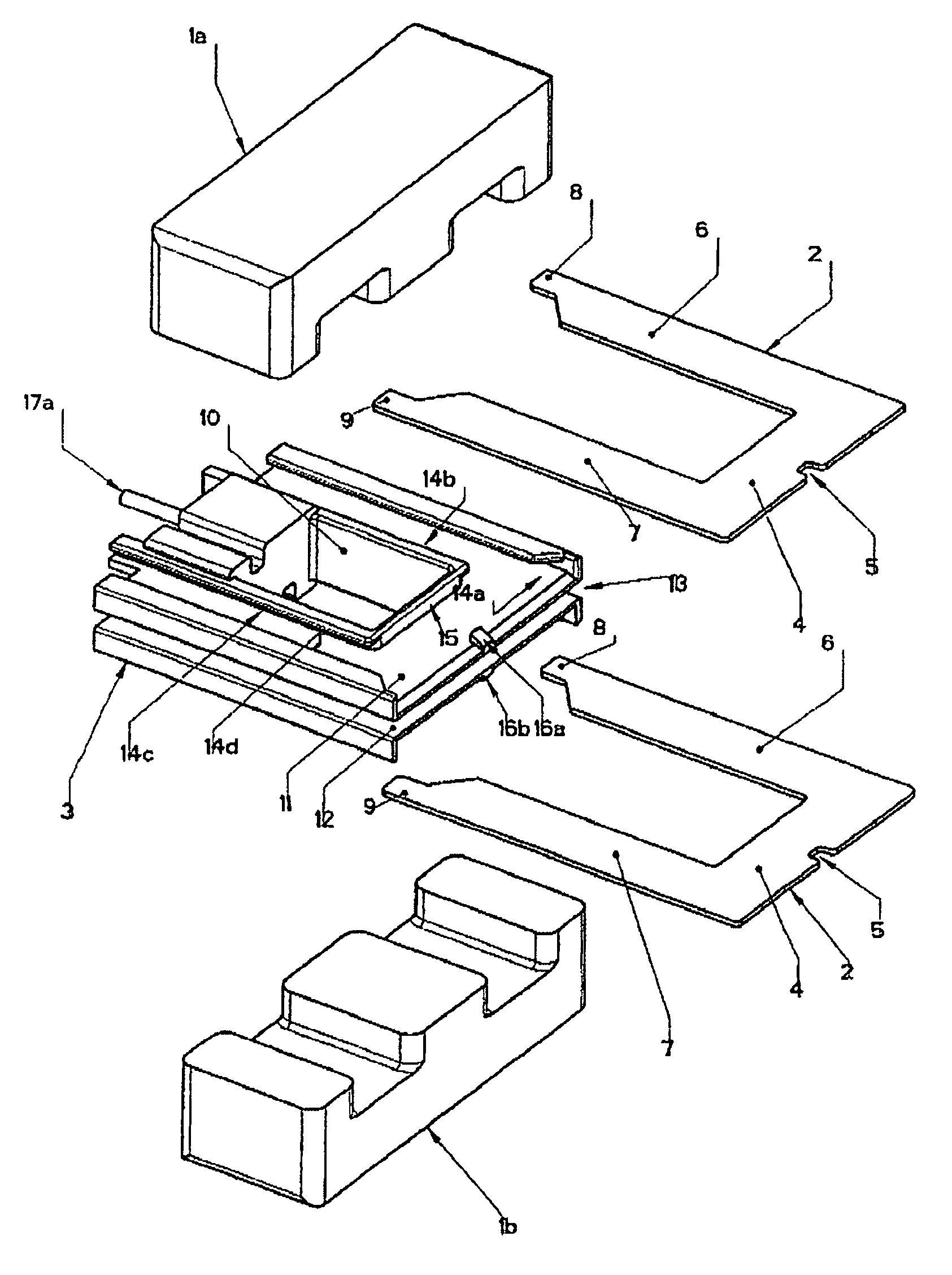
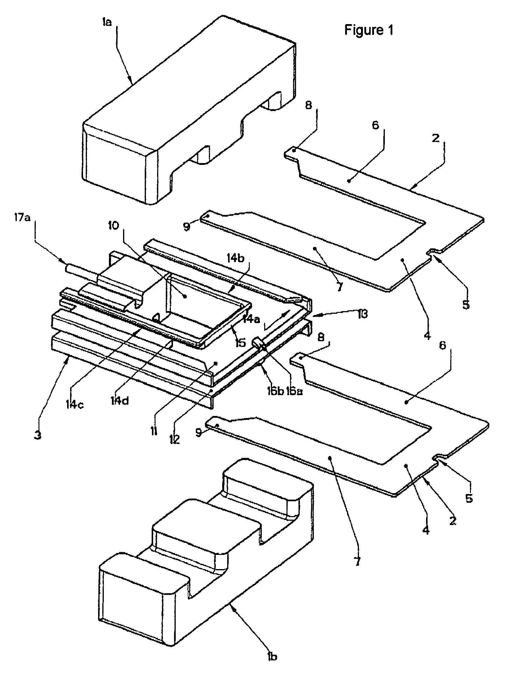
[0035]FIG. 1 shows essential components of an exemplary embodiment of the planar transformer according to the invention, to be specific a three-leg ferrite core comprising two halves 1a, 1b, two winding sheets 2 forming a secondary coil, and a coil former 3. The primary winding is not shown for the sake of a clearer overview.

[0036]The winding sheets 2 consist of a conductor material and are preferably punched out or eroded from a copper sheet and are tin-plated. They have an essentially U-shaped profile, that is to say they are open to one side. The upper cross-piece 4 of the U-shaped profile has at the center of the outer edge a small, essentially rectangular notch 5. Both ends of the cross-piece are adjoined by free legs 6, 7.

[0037]The thickness of the winding sheets 2 is small in comparison with the width of their cross-pieces 4 and of the legs 6, 7. The width of a predominant part of the legs 6, 7 corresponds essentially to the width of the cross-piece 4 in the region of the not...


PUM


Abstract

The invention aims to prevent the disadvantages of printed circuit board transformers with respect to their quality and safety, in particular in a performance range of greater than 150 VA with output voltages of less than 12 V. This is achieved by a planar transformer comprising a ferrite core (1a, 1b, 21a, 21b), at least one primary coil and at least one secondary coil, which can be connected on a printed circuit board and a coil body (3, 23), which encompasses part of the ferrite core (1a, 1b, 21a, 21b) and carries at least one secondary coil. According to the invention, each of the secondary coils (3, 23) carried by the coil body is configured from at least one winding metal sheet (2, 22), which is open on one side and can be plugged into the coil body (3, 23) and connected to the printed circuit board.

Description

FIELD OF THE INVENTION[0001]The invention relates to a planar transformer comprising a ferrite core, at least one primary coil and at least one secondary coil, which can be connected on a printed circuit board, and a coil former, which encloses part of the ferrite core and carries at least one secondary coil.BACKGROUND OF THE INVENTION[0002]As the requirement for the volume-related power density (VA / in3) of a switched-mode power supply increases, the requirements for its inductive components, in particular the main transformer or transformers, also increase. Therefore, for about 20 years, printed circuit card transformers of every conceivable design have increasingly being used, as a separate component or integrated into the main board of a power supply.[0003]One example of such a printed circuit card transformer is known from U.S. Pat. No. 5,010,314. Its primary and secondary coils are etched-in on printed circuit cards, which have a recess in their center, so that the printed circ...

Claims


Application Information

Patent Timeline
IPC IPC(8): H01F27/30H01F27/28
CPCH01F27/2847
Inventor PECK, JOACHIMPILNIAK, JURGEN
Owner DET INT HLDG LTD
Why Eureka
Try Eureka