Position/orientation measurement method, and position/orientation measurement apparatus

a technology of position/orientation measurement and measurement method, which is applied in the field of position/orientation measurement method and position/orientation measurement apparatus, can solve the problems of high position measurement precision and high orientation measurement precision, and achieve the effect of high precision

Active Publication Date: 2006-08-15
CANON KK
View PDF10 Cites 132 Cited by
  • Summary
  • Abstract
  • Description
  • Claims
  • Application Information

AI Technical Summary

Benefits of technology

[0039]The present invention has been made in consideration of the above problems, and has a

Problems solved by technology

A problem of alignment in mixed reality amounts to obtaining the position and orientation of an image sensing device in a scene (i.e., on a world coordinate system) in case of the video see-through system.
Likewise, such problem amounts to obtaining the position and orientation of the viewpoint of the observer or display in a scene in case of the optical see-through system.
However, with the former method that detects the indicators in the scene from the subjective viewpoint image obtained from the image sensing device as an object to be measured, since the moving amounts of the ind

Method used


Image

  • Position/orientation measurement method, and position/orientation measurement apparatus
  • Position/orientation measurement method, and position/orientation measurement apparatus
  • Position/orientation measurement method, and position/orientation measurement apparatus

Examples


first embodiment

[First Embodiment]

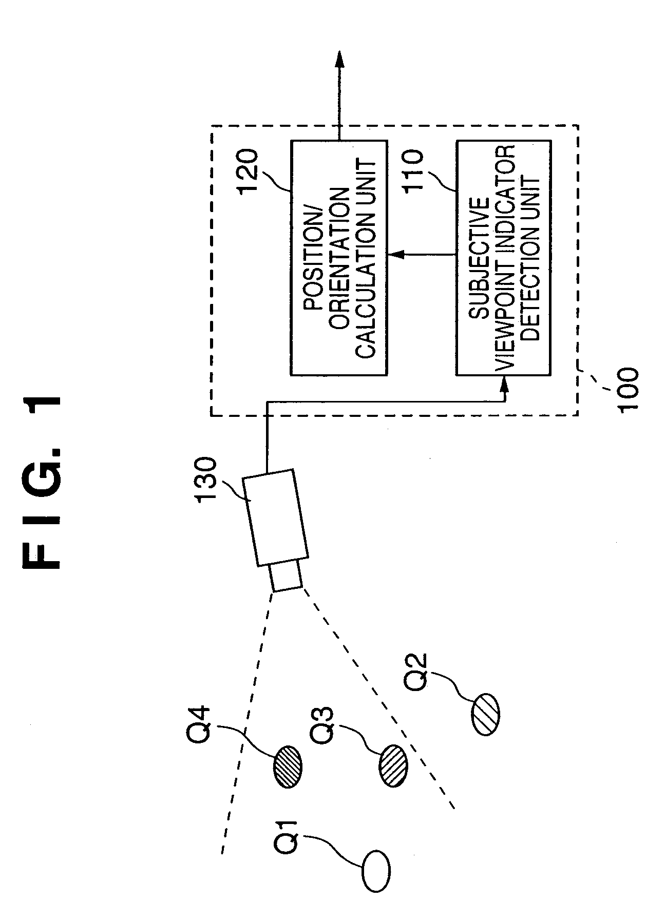
[0086]A position / orientation measurement apparatus according to this embodiment measures the position and orientation of an image sensing device. The position / orientation measurement apparatus and position / orientation measurement method according to this embodiment measures will be described hereinafter.

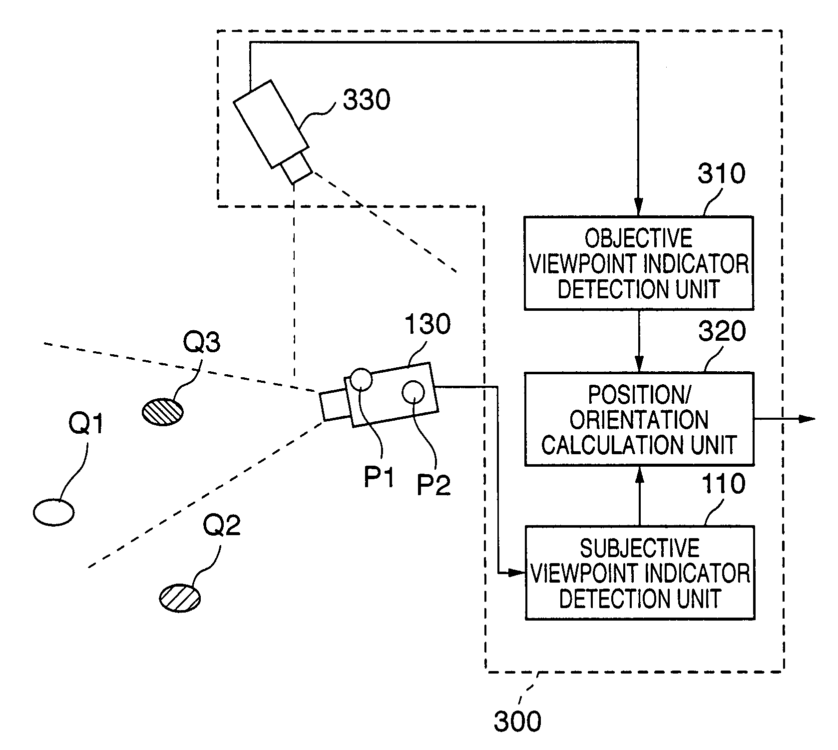
[0087]FIG. 3 is a schematic diagram showing the arrangement of a position / orientation measurement apparatus according to this embodiment. Note that the same reference numerals and symbols in FIG. 3 denote the same parts as those in FIG. 1, and a description thereof will be omitted. As shown in FIG. 3, a position / orientation measurement apparatus 300 according to this embodiment comprises a subjective viewpoint indicator detection unit 110, objective viewpoint indicator detection unit 310, position / orientation calculation unit 320, and objective viewpoint camera 330, and is connected to an image sensing device 130 to be measured.

[0088]The objective viewpoint camera 3...

second embodiment

[Second Embodiment]

[0133]A position / orientation measurement apparatus according to this embodiment measures the positions and orientations of two cameras mounted on a stereo video see-through HMD (Head Mount Display). The position / orientation measurement apparatus and position / orientation measurement method according to this embodiment will be described hereinafter.

[0134]FIG. 5 is a schematic diagram showing the arrangement of the position / orientation measurement apparatus according to this embodiment. Note that the same reference numerals and symbols in FIG. 5 denote the same parts as those in FIGS. 1 and 3. As shown in FIG. 5, a position / orientation measurement apparatus 500 according to this embodiment comprises subjective viewpoint indicator detection units 110R and 110L, objective viewpoint indicator detection unit 310, position / orientation calculation unit 520, and objective viewpoint camera 330.

[0135]Subjective viewpoint indicators Qk are laid out in the same manner as in the...

third embodiment

[Third Embodiment]

[0150]The first embodiment uses one objective viewpoint camera. However, the number of objective viewpoint cameras is not limited to one. When a plurality of objective viewpoint cameras are used to form the position / orientation measurement apparatus, expansion of the measurement range and improvement of measurement stability are expected.

[0151]FIG. 6 is a schematic diagram showing the arrangement of the position / orientation measurement apparatus according to this embodiment. Note that the same reference numerals and symbols in FIG. 6 denote the same parts as those in FIGS. 1 and 3. As shown in FIG. 6, a position / orientation measurement apparatus 600 according to this embodiment comprises objective viewpoint cameras 330a to 330d, objective viewpoint indicator detection units 310a to 310d, a subjective viewpoint indicator detection unit 110, and a position / orientation calculation unit 620.

[0152]Note that subjective and objective viewpoint indicators Q and P are laid ...


PUM


Abstract

A first error coordinate between the image coordinate of a first indicator, which is arranged on the real space and detected on a first image captured by a first image sensing unit, and the estimated image coordinate of the first indicator, which is estimated to be located on the first image in accordance with the position/orientation relationship between the first image sensing unit (with the position and orientation according to a previously calculated position/orientation parameter) and the first indicator, is calculated. On the other-hand, a second error coordinate between the image coordinate of a second indicator, which is arranged on the first image sensing unit and detected on a second image that includes the first image sensing unit, and the estimated image coordinate of the second indicator, which is estimated to be located on the second image in accordance with the position/orientation relationship between the first image sensing unit (with the position and orientation according to the position/orientation parameter), and the second indicator, is calculated. Using the first and second error coordinates, the position/orientation parameter is corrected.

Description

FIELD OF THE INVENTION[0001]The present invention relates to a technique for measuring the position and orientation of an image sensing device or an object that mounts the image sensing device.BACKGROUND OF THE INVENTION[0002]In recent years, studies about mixed reality that aims at seamless joint of real and virtual spaces have been extensively made. An image display apparatus that presents mixed reality is implemented by a video see-through system which superimposes and renders an image of a virtual space (e.g., virtual objects, text information, and the like rendered by computer graphics) generated in correspondence with the position and orientation of an image sensing device such as a video camera or the like on a real space image captured by the image sensing device, and displays these images.[0003]In addition, the image display apparatus is implemented by an optical see-through system which displays a virtual space image generated in correspondence with the position and orient...

Claims


Application Information

Patent Timeline
IPC IPC(8): H04N7/18G01B11/00G01B11/26G06F3/033G06F3/042G06T1/00G06T7/60
CPCG06F3/0325G01B11/00G01B11/002
Inventor SATOH, KIYOHIDEUCHIYAMA, SHINJIANABUKI, MAHORO
Owner CANON KK
Why Eureka
Try Eureka