Co-channel interference receiver

a receiver and co-channel technology, applied in the field of wireless communications, can solve the problems of ineffective schemes, inability to properly account for real-world wireless communication signals in conventional systems, and inability to realize real-time operation, so as to reduce the number of uncertain bit estimates, space and polarization diversity, the effect of reducing the number of uncertain bits

Inactive Publication Date: 2006-08-15
COLLISION COMM
View PDF15 Cites 76 Cited by
  • Summary
  • Abstract
  • Description
  • Claims
  • Application Information

AI Technical Summary

Benefits of technology

[0015]The analog front end may further include one or more antennas each configured to receive a corresponding composite waveform signal from the plurality of transmitters. In one such embodiment, the one or more antennas is a singly polarized antenna. Alternatively, the one or more antennas is a dual polarized antenna adapted with two polarization ports, thereby providing polarization diversity. Alternatively, the one or more antennas include two or more dual polarized antennas, each adapted with two polarization ports, thereby providing space and polarization diversity.
[0016]In an embodiment where the multiuser detector module is configured to operate with the low complexity linear MMSE algorithm with partially quantized prior information, the multiuser detector module includes a turbo MUD module, a combiner module, an error correction module, and a thresholding module. The turbo MUD module is adapted to provide estimates of individual bits for each of the K co-channel interfering signals. The estimates are iteratively applied in a feedback loop, which includes the error correction module, until an error rate associated with the bits drops below a predetermined figure. The combiner module is operatively coupled to the turbo MUD, and is adapted to combine recomputed bit estimates output by the turbo MUD with quantized bit values on a next iteration. The thresholding module is operatively coupled to the output of the error correction module, and is adapted to assign a quantized value for each bit estimate above a predetermined threshold, and to pass through those quantized bit values to the combiner module, thereby enabling partially quantized prior information. In one such embodiment, the error correction module on each subsequent iteration processes a combination of recomputed bit estimates output by the turbo MUD and quantized bit values output by the thresholding module, and provides its output back to the tur

Problems solved by technology

Such schemes are inefficient in that given sufficient signal to noise ratio or coding redundancy, more communicators could use the allocated bandwidth if provided with a means for detecting the excess signal margin, as well as a means for demodulating signals in the presence of interference.
In short, despite the advancements in wireless transmission and reception, conventional systems do not properly account for the real world wireless communication signals that suffer from signal degradation such as interference and multipath problems.
Each of these transmissions are associated with real-time problems of multipath and co

Method used


Image

  • Co-channel interference receiver
  • Co-channel interference receiver
  • Co-channel interference receiver

Examples


Embodiment Construction

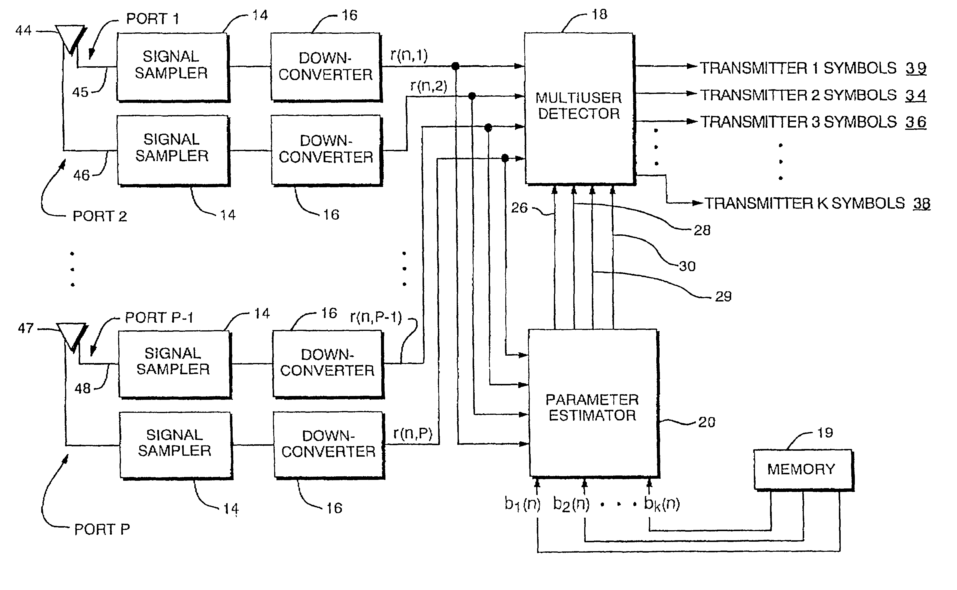
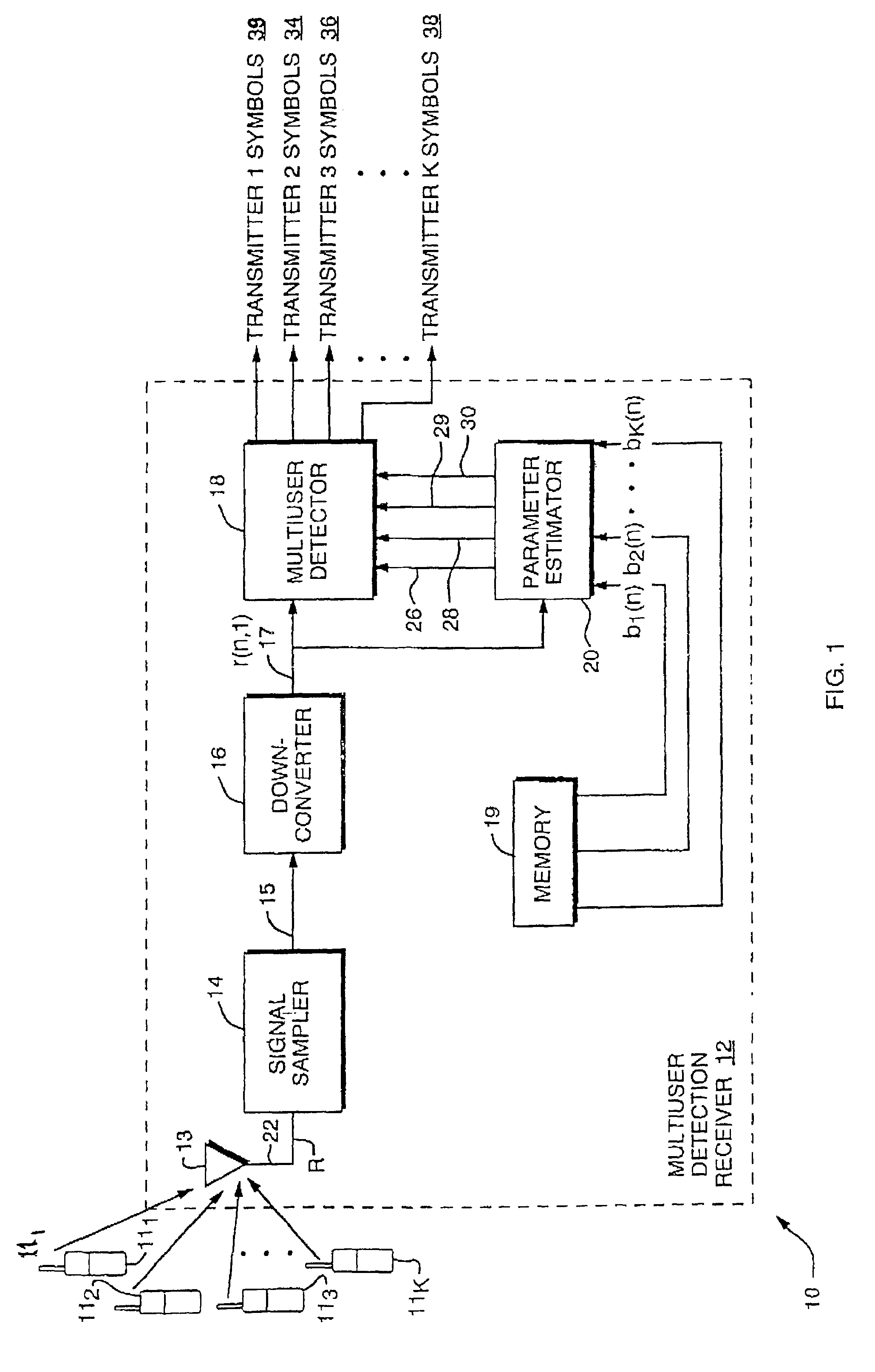
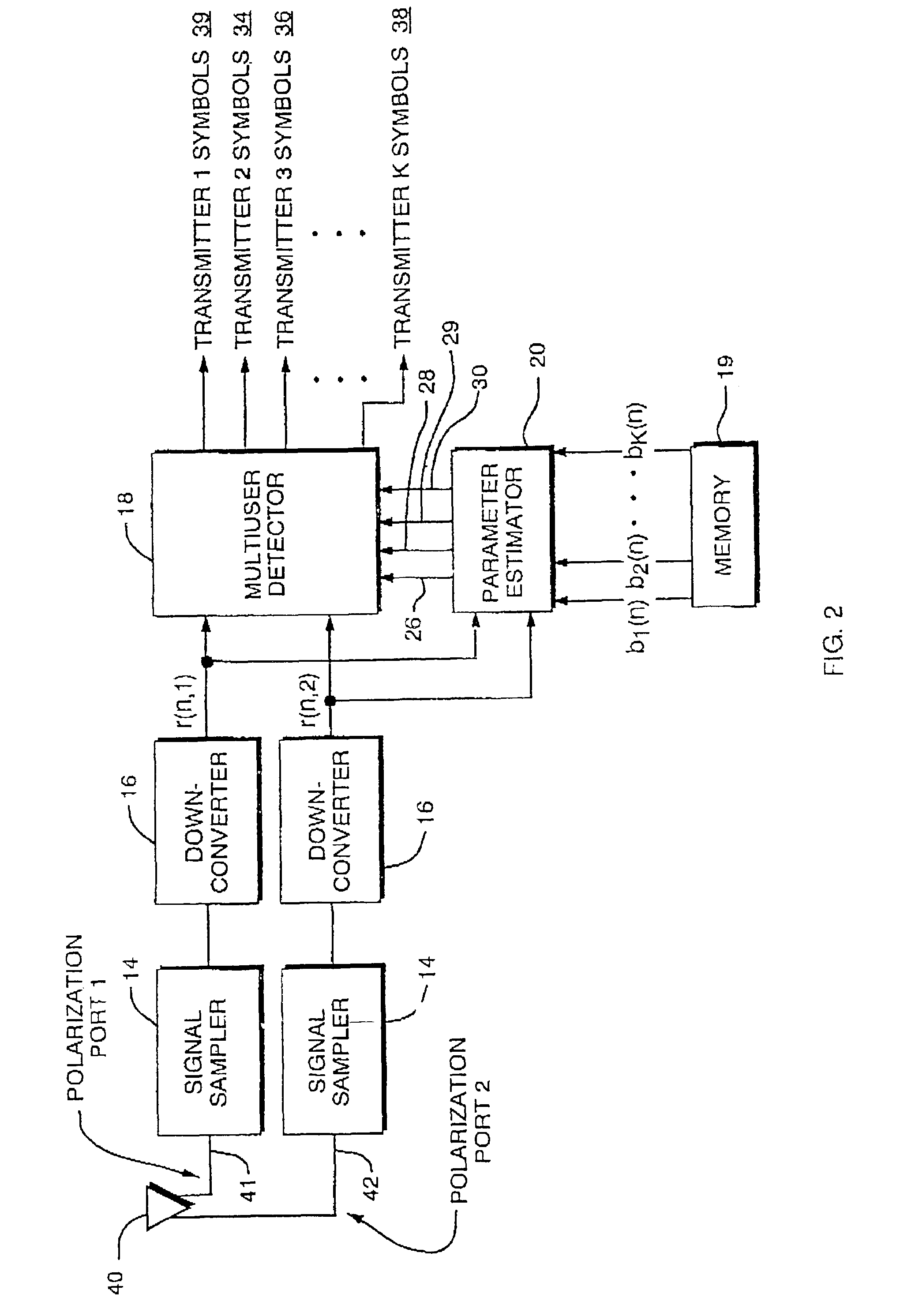
[0040]In present day communication systems, a central controller normally assigns one communicator to each channel, during a communication channel setup period. Channels may be some combination of a time slot, a frequency, and a spreading code. In most systems, channels are re-used in distant regions, thereby giving rise to co-channel interference. If there is a large distance between the regions wherein the re-use occurs, then signal attenuation reduces the co-channel interference to tolerable levels. This is a necessary result, as conventional receivers cannot demodulate a signal in the presence of significant co-channel interference.

[0041]A Co-Channel Interference Receiver configured in accordance with the principles of the present invention can jointly demodulate two or more signals transmitted on the same channel. Systems utilizing an embodiment of the Co-Channel Interference Receiver could use a similar channel setup format, but the channel assignments would not be limited to ...


PUM


Abstract

A digital receiver automatically detects and non-coherently demodulates a multiplicity of interfering digitally modulated signals transmitted simultaneously at approximately the same carrier frequency. The receiver includes one or more antenna inputs (e.g., polarization and/or space diverse), a parameter estimator module, and a multiuser detector for estimating the data transmitted by each interfering signals and adapted to operate with at least one of a MUD algorithm with partially quantized prior information and a MUD algorithm based on prewhitened data.

Description

RELATED APPLICATIONS[0001]This application claims the benefit of U.S. Provisional Application No. 60 / 398,451, filed Jul. 24, 2002. This application is a continuation-in-part of U.S. application Ser. No. 10 / 228,787 filed Aug. 26, 2002, which claims priority to U.S. Provisional Application No. 60 / 372,956, filed Apr. 16, 2002. This application is also a continuation-in-part of U.S. application Ser. No. 10 / 105,918, filed Mar. 25, 2002. This application is related to U.S. application Ser. No. 10 / 423,695, filed Apr. 25, 2003, This application is related to U.S. application Ser. No. 10 / 423,655, filed Apr. 25, 2003. Each of these applications is herein incorporated in its entirety by reference.STATEMENT OF GOVERNMENT INTEREST[0002]The present invention was made with United States Government support under a United States Government Contract. The United States Government has certain rights in this invention.FIELD OF THE INVENTION[0003]The invention relates to wireless communications, and more...

Claims


Application Information

Patent Timeline
IPC IPC(8): H04B7/02H03D1/00H04L1/00H04L27/06
CPCH04B1/7105H04B1/71055H04L1/0048H04L25/0204H04L25/0248H04L25/03171H04L25/03203H04L25/03331H04L25/0246H04L25/0228H04L2025/03611H04L25/03286
Inventor TAYLOR, MATTHEW AMACLEOD, ROBERT BLEARNED, RACHEL ENIEDZWIECKI, JOSHUA DBROMMER, KARL DMCELWAIN, THOMAS P
Owner COLLISION COMM
Why Eureka
Try Eureka