Communication apparatus

a communication device and communication technology, applied in electrical devices, line monitoring circuits, pictoral communication, etc., can solve the problems of circuit cost, circuit space, and difficulty in meeting the above standards at the same time, so as to save space, and reduce the cost of the apparatus.

Inactive Publication Date: 2006-08-15
CANON KK
View PDF13 Cites 6 Cited by
  • Summary
  • Abstract
  • Description
  • Claims
  • Application Information

AI Technical Summary

Benefits of technology

[0041]It is a primary object of the present invention to provide a communication apparatus that can be actualized at low costs and can save its space in communication apparatuses that connect to an analog public line for communication.
[0042]It is therefore a major object of the present invention to decrease costs of the apparatus by executing a hook detection by utilizing a current from a line even during a capture of the line and during a wait in non-ringing call receipt setting (for preventing a telephone set connected to a terminal T1 / T2 from ringing triggered by a CI signal).
[0043]It is another object of the present invention to remove an influence of the telephone set that is in the process of communications and dialing, which is to occur due to an execution of the hook detection using the current from the line.
[0044]It is still another object of the present invention to detect the hooking of the telephone set while eliminating the influence of the telephone set during the communications and the dialing, and to surely detect that the dialing is suspended midways.
[0045]It is a further object of the present invention to provide a communication apparatus having no DC power source dedicated for hook detection, capable of surely detecting a hook-state during off-hook dialing, and capable of eliminating mis-dialing in the case where when dialing is executed from a FAX side in an off-hook-state of the telephone set and a mistake is noticed in inputting a telephone number, a correct telephone number is entered after on-hooking / off-hooking of the telephone set.

Problems solved by technology

If a circuit for this insulating separation is provided, there arises a problem, wherein this circuit is costly and needs both a wider space for use and extra electric power of consumption.
A problem in the case of providing this noise preventive circuit is that this circuit is costly and needs its space.
If it is required to detect the off-hook of the telephone set as the second communication means CS62 by use of a current value smaller than 5 to 10 mA, however, even though the HOOK detector is constructed as the standards require, there is still such a problem that it is difficult to meet the above standards simultaneously.
This causes a problem in which the off-hook of the telephone set 2 cannot be detected.
Moreover, according to the conventional method described above, there is no means for preventing the telephone set to ring, so that when the communication apparatus is not in the operation state, the arrived calling signal invariably reaches the telephone set, resulting in such a problem that the telephone set is to ring in the case where the telephone set is not desired to ring.
Further, according to the conventional method disclosed in Japanese Patent No. 3055343, one off-hook detecting circuit is provided for one extension phone, and therefore the same problem as the above might occur.
This configuration conduces to a problem of increasing the number of internal circuits of the apparatus and the costs thereof, enlarging a circuit space and causing a rise in the electric power of consumption.
In the conventional facsimile apparatus FS11, however, the DC power source 218 is normally incorporated into a power unit, and a problem is that the DC power source 218 itself is a factor for increasing the costs of the power unit.
Further, in the conventional facsimile apparatus FS11, a cable and a connector are needed for connecting the power unit to the NCU (network control circuit unit), and hence there arises a problem in which steps for connecting these components are required, and this is also a factor for further increasing the costs.
According to the conventional facsimile apparatus FS11, however, the DC power source 218 is normally incorporated into the power unit, the problem is that the DC power source 218 itself is the factor for increasing the costs of the power unit.
A further problem is that the connector is needed for connecting the power unit to the NCU (network control circuit unit), and steps for connecting these components are required, which causes a large increase in the costs.

Method used


Image

  • Communication apparatus
  • Communication apparatus
  • Communication apparatus

Examples


first embodiment

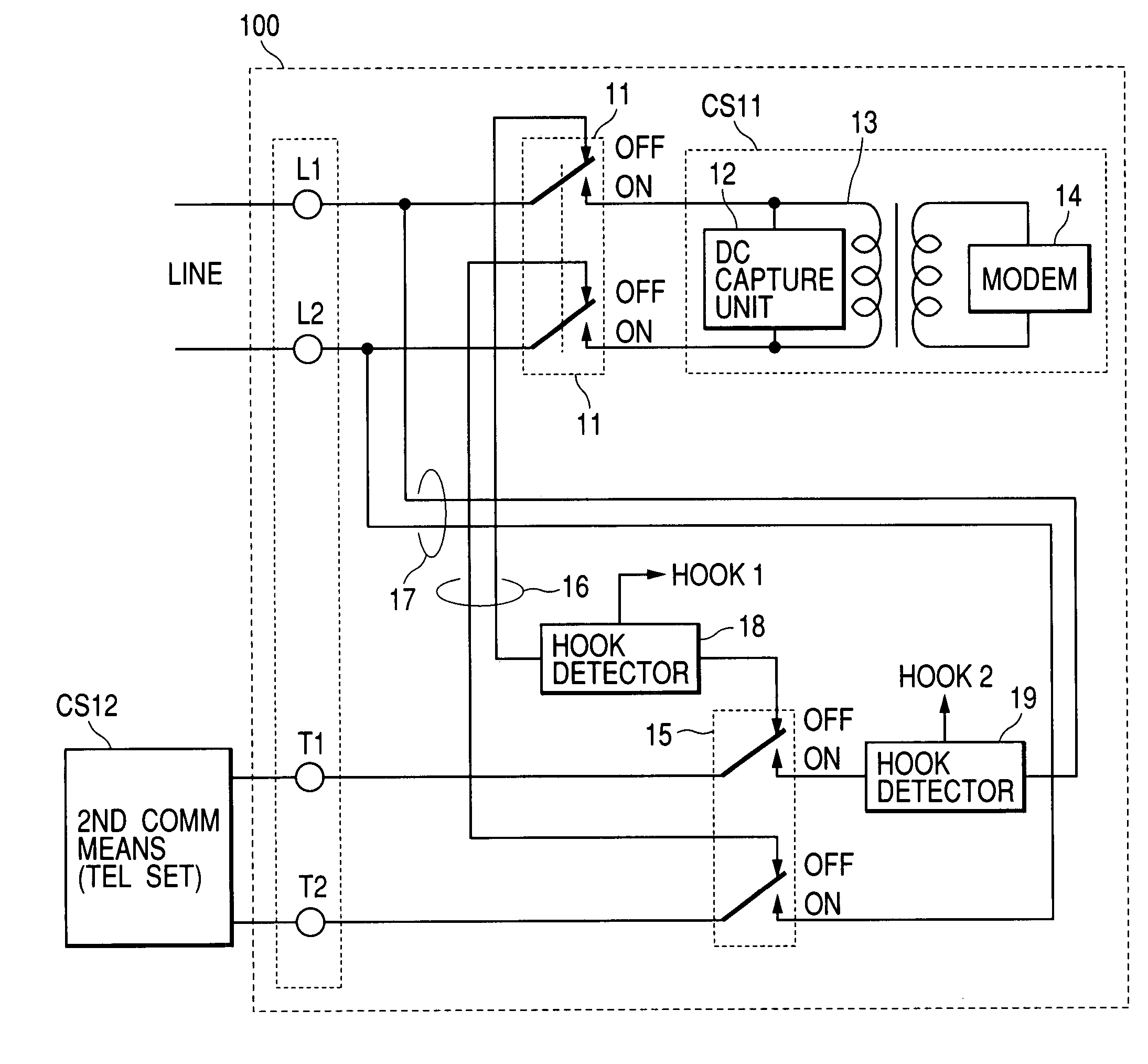
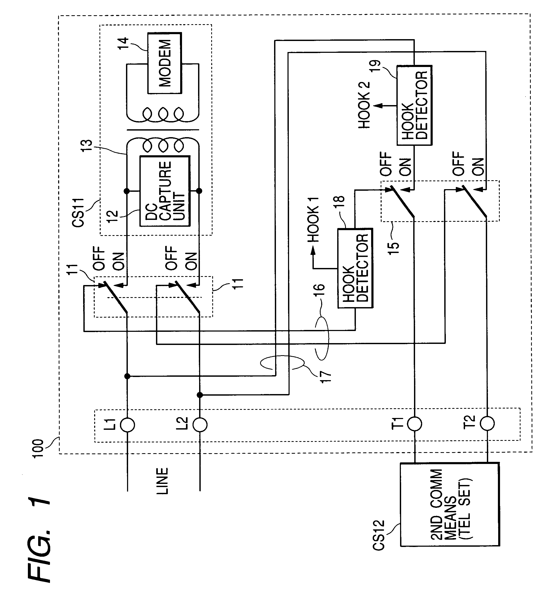
[0061]FIG. 1 is a block showing a communication apparatus 100 according to the present invention.

[0062]The communication apparatus 100 includes a first communication means CS11 and further has a modular connector, etc., defined as a connecting means for connecting a second communication means CS12. The first communication means CS11 is defined as a communication means for performing, for example, facsimile communications. The second communication means CS12 is a telephone set.

[0063]The communication apparatus 100 is connected via two lines L1, L2 to an analog public line. The telephone set defined as the second communication means CS12 is connected to the communication apparatus 100 via two lines T1, T2 as a connecting means of the second communication means.

[0064]The facsimile apparatus as the communication apparatus 100 includes a CML relay 11, the first communication means CS11, an H relay 15, a first route means (or first path means) 16, a second route means (or second path mean...

second embodiment

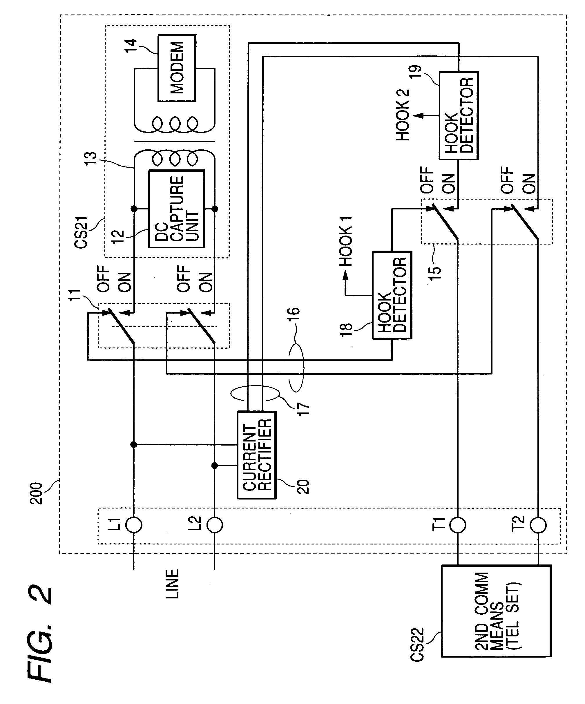
[0097]FIG. 2 is a block diagram showing a communication apparatus 200 according to the present invention.

[0098]The communication apparatus 200 includes a first communication means CS21 and further has a modular connector, etc., defined as a connecting means for connecting a second communication means CS22. The first communication means CS21 is defined as a communication means for performing, for example, the facsimile communications. The second communication means CS22 is a telephone set as the second communication means CS12.

[0099]Moreover, the second route means 17 of the communication apparatus 200 has a current rectifier 20. The current rectifier 20 exists on the second route means 17 and is provided closer to the line than the H relay 15.

[0100]FIG. 3 is a circuit diagram showing one example of the current rectifier 20.

[0101]The current rectifier 20 uses, as illustrated in FIG. 3, four pieces of unidirectional devices (e.g., diodes). In this current rectifier 20, anode and catho...

third embodiment

[0108]FIG. 4 is a block diagram showing a communication apparatus 300 according to the present invention.

[0109]The communication apparatus 300 includes a first communication means CS31 and further has a modular connector, etc., defined as a connecting means for connecting a second communication means CS32. The first communication means CS31 is defined as a communication means for performing, for example, the facsimile communications. The second communication means CS32 is a telephone set as the second communication means CS12.

[0110]Moreover, the second route means 17 of the communication apparatus 300 has an H detection relay 21. The H detection relay 21 exists on the second route means 17 and is provided closer to the line than the H relay 15 in the communication apparatus 300. In the communication apparatus 300, the H detection relay 21 is attached to one of two wires and may also be attached to both of the two wires.

[0111]When switching on the H detection relay 21, the second rou...


PUM


Abstract

Disclosed is a communication apparatus connected to an analog public line, which can be actualized at low costs and can save its space. This communication apparatus includes a first communication means connected to a telephone line, for performing communications, and a connecting means for connecting a second communication means connected to the telephone line via the first communication means and thus performing communications. In this communication apparatus, the first communication means has a first switch means for connecting the telephone line to the first communication means or the second communication means, a first route means for connecting the second communication means to the telephone line via the first switch means, a second route means for connecting the second communication means directly to the telephone line, a second switch means for connecting the second communication means to the first route means or the second route means, a first hook detecting means connected to the first route means, and a second hook detecting means connected between the telephone line on the second route means and the second switch means.

Description

BACKGROUND OF THE INVENTION[0001]1. Field of the Invention[0002]The present invention relates to a communication apparatus for detecting a hook-state of a second communication means such as a telephone set in facsimile apparatus and data communication apparatus that can be utilized by connecting the second communication means thereto.[0003]2. Related Background ArtCONVENTIONAL EXAMPLE 1[0004]FIG. 6 is a diagram showing a conventional communication apparatus 600.[0005]This conventional communication apparatus 600 is utilized in such configuration that communication means CS61 and CS62 are connected to one analog public line (PSTN: Public Switched Telephone Network), and a telephone set defined as the second communication means CS62 is connected to a facsimile apparatus defined as the first communication means CS61.[0006]In the conventional communication apparatus 600, a line connects to terminals L1 and L2, while the telephone set connects to terminals T1, and T2. The first communica...

Claims


Application Information

Patent Timeline
Patent Type & Authority Patents(United States)
IPC IPC(8): H04M11/00H04M1/82H04N1/327
CPCH04M1/82H04N1/32704H04N1/32708H04N1/32763H04N1/32719H04N1/32728H04N1/32745H04N1/32717
Inventor SAITO, HITOSHIFUJISE, SHUNICHI
Owner CANON KK
Why Eureka
Try Eureka