Apparatus for determining fibre lengths and fibre length distribution from a fibre material sample, especially in spinning preparation

Inactive Publication Date: 2006-08-22
TROTZSCHLER
View PDF18 Cites 4 Cited by
  • Summary
  • Abstract
  • Description
  • Claims
  • Application Information

AI Technical Summary

Benefits of technology

[0013]Because a conveying device, a clamping device and a combing device, for example at least one combing roller, as well as transfer devices are provided, wherein not only the operation of the afore-mentioned devices as such but also the transfer between the devices is to be effected automatically, the same preconditions for the preparation of all samples are created. In particular, anomalies attributable to manual handling are excluded. It is a further particular advantage that the apparatus can be used in the works directly at the machines or fibre sliver cans. Added to the quicker sample preparation within the apparatus is the considerable time saving gained by carrying out testing away from the fibre laboratory. The fibre lengths and fibre length distribution ascertained can be used for optimum setting of the carding machines (fibre shortening / nep count) and can also be utilised in reducing or removing short fibres from the processed fibre material.
[0021]Advantageously, the determined measured values of the fibre lengths (staple) and the fibre length distribution from the feed region of the card, e.g. fibre flock supply, and from the delivery region of the card, e.g. the card sliver in the spinning can, are compared with one another. The measured values of the fibre length distribution determined from the sliver in aggressive and gentle processing are preferably compared with one another. The measured values of the fibre length distribution determined from the sliver in aggressive and gentle settings of individual assemblies, e.g. clothed revolving card top or fixed card top, are preferably compared with one another. Advantageously, fibre shortening and / or fibre damage due to processing on the card are ascertained from the comparison of the measured values. A fibre damage sensor (fibre stress sensor FSS) is created by the above-mentioned measures. It is possible to obtain accurate information about staple shortening caused by the card. By adjusting operating elements or machine elements, it is therefore possible to achieve the least possible damage to the fibre at the card.

Problems solved by technology

The known sample preparation is time-consuming.
It is a further disadvantage that owing to the individual handling of the sample preparation, the samples are not uniformly consistent.
Finally, it is inconvenient that a fibre measurement at the location of the spinning machine is not possible.

Method used


Image

  • Apparatus for determining fibre lengths and fibre length distribution from a fibre material sample, especially in spinning preparation
  • Apparatus for determining fibre lengths and fibre length distribution from a fibre material sample, especially in spinning preparation
  • Apparatus for determining fibre lengths and fibre length distribution from a fibre material sample, especially in spinning preparation

Examples


Embodiment Construction

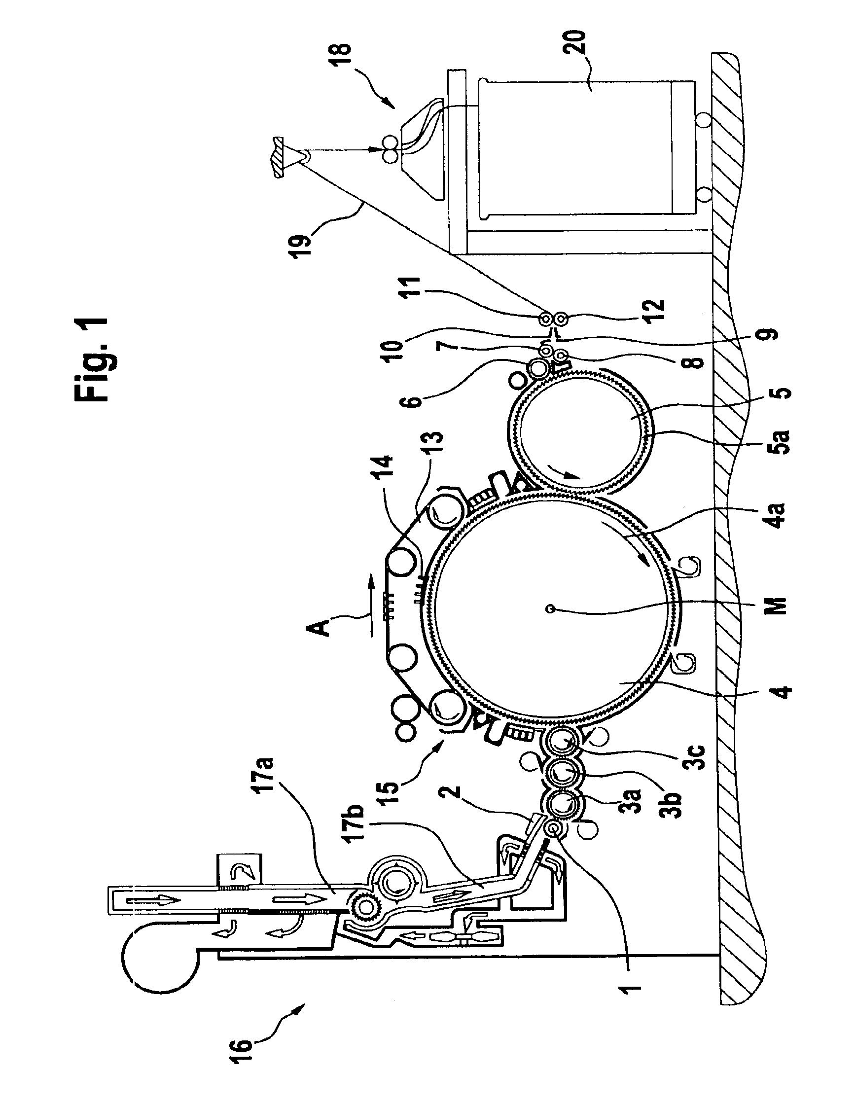
[0033]FIG. 1 shows a carding machine 15, for example, a high performance card DK 903 made by Trützschler GmbH & Co. KG of Mönchengladbach, Germany, with feed roller 1, feed table 2, licker-ins 3a, 3b, 3c, cylinder 4, doffer 5, stripping roller 6, squeezing rollers 7, 8, web-guide element 9, web funnel 10, take-off rollers 11, 12 and revolving card top 13 with carding segments 14. The directions of rotation of the rollers are shown by respective curved arrows. The letter A denotes the working direction. A chute feed 16 for the flocks, for example, a Direktfeed DFK made by Trützschler GmbH & Co. KG, is located upstream of the card 15. The chute feed 16 comprises an upper reserve hopper 17a and a lower feed chute 17b. The pneumatically compacted (not illustrated) fibre flock material is removed at the end of the feed chute 17b by the feed roller 1 and directed through the gap between feed roller 1 and feed table 2 to the high-speed licker-in 3a. A can coiler 18 is located at the delive...


PUM

PropertyMeasurementUnit
Lengthaaaaaaaaaa
Speedaaaaaaaaaa
Widthaaaaaaaaaa

Abstract

In an apparatus for determining fibre lengths and fibre length distribution from a fibre material sample, especially in spinning preparation, collected fibre material is automatically conveyable by a conveyor device, is arranged to be supplied to a take-up device that grips it, is separable from the conveyor device and transportable to at least one rotating combing device, each end region of the collected fibre material protruding from the take-up device being combable by combing device, and subsequently detectable by a measuring device. The apparatus permits within a short time a sample preparation founded on a uniform basis and an accurate measurement of the samples.

Description

CROSS REFERENCE TO RELATED APPLICATION[0001]This application claims the priority of German Patent Application No. 103 11 345.2, which is incorporated herein by reference.BACKGROUND OF THE INVENTION[0002]The invention relates to an apparatus for determining fibre lengths and fibre length distribution from a fibre material sample, especially in spinning preparation. In such apparatus, sample preparation elements may be located upstream of the measuring, evaluating and indicating device, said preparation elements comprising a clamping device and a combing element for the treatment of collected fibre material, the combing element producing a fibre fringe that is used for the measurement.[0003]In the practical operation of spinning, fibre slivers taken from production are brought into a fibre laboratory, where the following testing is carried out:[0004](a) several slivers are placed by hand in clamps previously opened by hand and are carefully, that is, homogeneously, distributed across ...

Claims


Application Information

Patent Timeline
IPC IPC(8): D01B3/04D01G15/00D01G31/00D01H13/26
CPCD01G31/006D01G31/00G01B11/02
Inventor BREUER, ACHIMCORRALES, ARREGUI PEDRO
Owner TROTZSCHLER
Why Eureka
Try Eureka