Light gauge metal truss system and method

a technology of metal trusses and light gauges, applied in the field of trusses, can solve the problems of reducing the quality of girders, difficulty in engaging chord members with truss clips and other fixtures, and adding to the cost of fabricating trusses, and achieve the effect of easy engagement of truss clips

Inactive Publication Date: 2006-08-22
INNOVATIVE STEEL TECH
View PDF57 Cites 40 Cited by
  • Summary
  • Abstract
  • Description
  • Claims
  • Application Information

AI Technical Summary

Benefits of technology

[0013]It is still another object of the invention to provide a truss system with truss chord members which easily engage truss clips and other fixtures.

Problems solved by technology

In the construction field, structural members and fixtures are increasingly formed from light gauge metal due to the rising cost and declining quality of wood.
Further by way of example, the angle of the inclined portion relative to the base may cause difficulties in engaging the chord member with truss clips and other fixtures.
However, box-shaped members are difficult to fabricate which adds to the expense of fabricating the truss and reduces the flexibility in providing trusses of differing dimensions.
The above-referenced French patent does not disclose or suggest structural members having sufficient size and strength to bear the loads subjected to a web member in a long span truss.
Heretofore, such two-piece box-shaped members have not been made in such sizes or used as load bearing web members in trusses.
However, in the fabrication of trusses it is not necessary or desirable to pre-position holes along the entire length of the chord member.

Method used


Image

  • Light gauge metal truss system and method
  • Light gauge metal truss system and method
  • Light gauge metal truss system and method

Examples


Embodiment Construction

[0038]The present invention is directed to truss systems wherein the structural members and fixtures are formed from light gauge metal. The gauge of the metal may vary depending upon the specific application, but is typically selected from the gauges of metal including 10, 12, 14, 16, 18, 20, and 22.

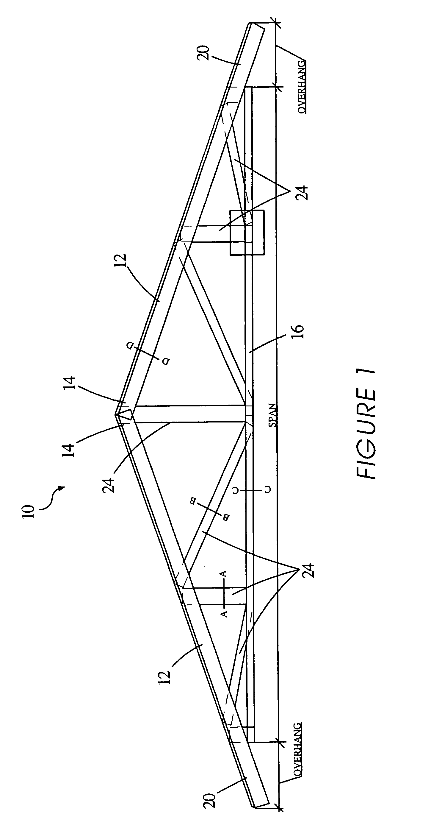
[0039]FIG. 1 illustrates a truss according to one aspect of the present invention. With reference to FIG. 1, the truss 10 is formed by coupling a pair of upper truss chord members 12 at the upper ends 14 thereof to form a peak. A lower chord member 16 is coupled at each end 18 thereof to the lower end 20 of one of the upper chord members 22. A plurality of web members 24 interconnect the upper and lower chord members 12,16. Each of the web members 24 is coupled at one end to an upper chord member 12 and at the other end to the lower chord member 16.

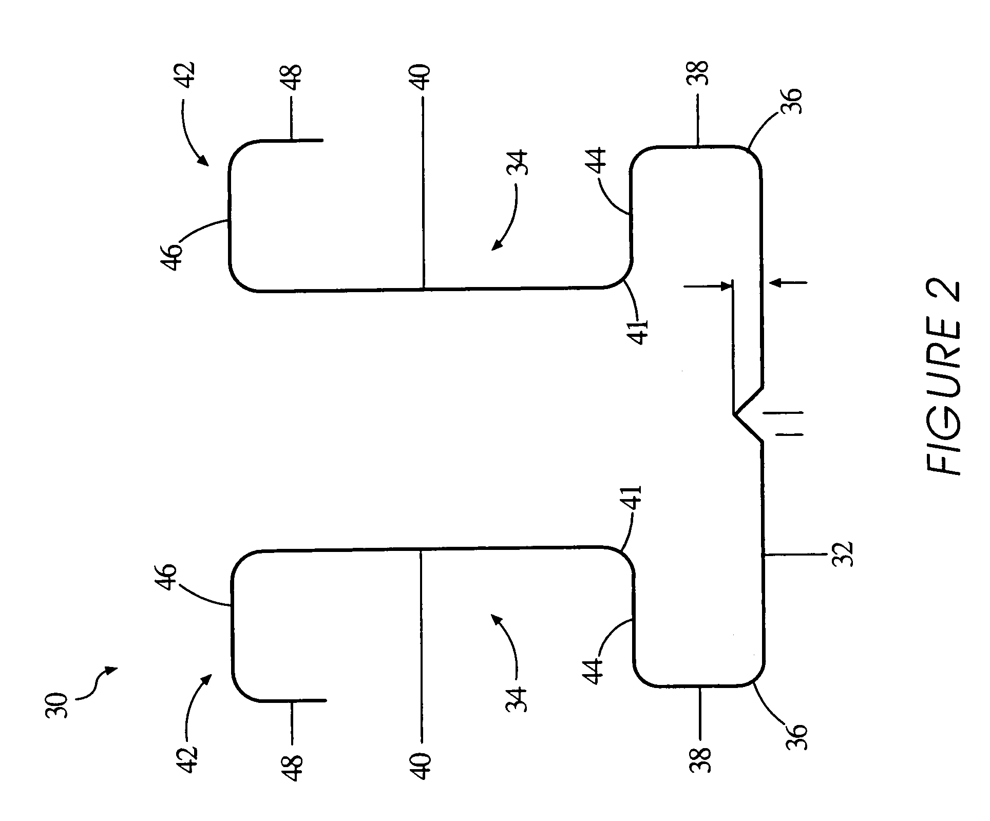
[0040]FIG. 2 illustrates one embodiment of an elongated truss chord member according to the present invention. With reference to FIG. 2, the ...


PUM

PropertyMeasurementUnit
depthaaaaaaaaaa
relative angleaaaaaaaaaa

Abstract

A truss system wherein the structural components and fixtures are formed from light gauge metal. The trusses are fabricated from roll formed truss chord members and truss web members. The truss chord members are roll formed to have a generally U-shaped cross-section with a base and two substantially parallel legs with recessed web attachment faces and outwardly extending stiffening flanges to improve structural capacity thus improving the strength-to-weight ratio of the chord member and minimizing costs. The truss web members are formed by nesting two roll formed C-shaped members to form a web member which is box-shaped in cross section. The web members provide the structural advantages of a box-shaped member and the ease and flexibility of a roll formed member. The truss system and method provides improved means and methods for positioning and attaching the web members to the chord members as well as improved truss clips for resistance to uplifting forces and improved truss jack clips for forming hip connections.

Description

CLAIM OF PRIORITY[0001]This Application is a divisional of and claims benefit of application Ser. No. 09 / 856,531 filed May 29, 2001 now U.S. pat. No. 6,658,809 entitled “LIGHT GAUGE METAL TRUSS SYSTEM AND METHOD”, which claims the benefit of U.S. Provisional Patent Application Ser. No. 60 / 207,200, filed May 26, 2000.BACKGROUND OF THE INVENTION[0002]The present invention relates to a truss system used in the construction of commercial and residential buildings. More particularly, the present invention relates to a truss system using roll-formed light gauge metal truss members and fixtures.[0003]In the construction field, structural members and fixtures are increasingly formed from light gauge metal due to the rising cost and declining quality of wood. Components formed from light gauge metal are preferred over wood in many applications because the metal components are lighter in weight, stronger, consistent in quality, not subject to shrinkage, and resistant to fire and insect infest...

Claims


Application Information

Patent Timeline
Patent Type & Authority Patents(United States)
IPC IPC(8): E04C3/30E04C3/04E04C3/07E04C3/11
CPCE04C3/07E04C3/11E04C2003/0413E04C2003/0421E04C2003/043Y10T428/12361E04C2003/0465E04C2003/0473E04C2003/0486E04C2003/0491E04C2003/0434
Inventor COLLINS, HARRY J.
Owner INNOVATIVE STEEL TECH
Why Eureka
Try Eureka