Ultrasonic gas flowmeter as well as device to measure exhaust flows of internal combustion engines and method to determine flow of gases

a gas flowmeter and ultrasonic technology, applied in the direction of volume/mass flow measurement, measurement devices, instruments, etc., can solve the problem of difficult construction of capacitive transducers, and achieve the effect of more accurate and reliable detection

Active Publication Date: 2006-08-22
AVL LIST GMBH
View PDF3 Cites 84 Cited by
  • Summary
  • Abstract
  • Description
  • Claims
  • Application Information

AI Technical Summary

Benefits of technology

[0034]This object is achieved according to the invention in that the sound transducers are designed as capacitive ultrasonic transducers for the generation of sound as well as for the reception of time transient sound signals, and devices to level the gas temperature profile of the flow, and to minimize the influence of the temperature profile on the flow measurement.
[0040]The transducer is advantageously provided with a plurality of separately accessible or readable areas in a linear or a plane arrangement. This make the avoidance of pocket holes possible relative to the transducer reception, which could cause additional turbulence of the flow in the region of the ultrasound path. These so-called “array transducers” are preferably manufactured by means of the aforementioned technologies. They have the advantage to make possible the characteristic of being oriented at an angle relative to the face of the transducer for the transmission or reception of sound. Flush-mounted installation of the ultrasonic transducer in the measuring pipe is thereby possible even at oblique irradiation by ultrasonic waves in the pipe. Individual areas of the array transducer are selected with the electric transmission signal at periodic discrete intervals in the use as transmitter. In the use as receiver, the individual reception signals are evaluated at a delayed time. In both types of operation, the angle characteristic of the transducer can be influenced by the variation of the periodic intervals, and the acoustic drift as well as the acoustic breaking phenomenon can be advantageously counter-acted thereby.
[0043]A rotatable mount of one or several transducers achieves successfully in a similar manner that a corresponding correction angle can be provided in the acoustic radiation so that the acoustic beam of the transmitter hits directly the receiver surface with its maximal sound level even at a high flow velocity or at a high temperature difference between the pipe wall and the flowing gas. In addition, the transducer is movably mounted in such a manner that the incoming and outgoing angle of the acoustic beam relative to the pipe axis can be changed by rotating the transducer.
[0044]Furthermore, a high temperature difference between the pipe wall and the flowing gas is decreased or avoided by means of a heating device for the wall of the measuring pipe, possibly also for the sound transducer. It is proposed thereby to match, as much as possible, the pipe temperature to the actual temperature of the flowing gas.
[0054]The capacity of the capacitive ultrasonic transducer represents an RC element (resistance capacitance) together with the coupling resistance of the bias voltage and it is thereby a low-pass filter for interferences of the bias voltage. Since there is now the same voltage at the non-inverting input of the amplifier, namely the bias voltage (possibly separate from the transducer potential by means of the above described capacity), it is advantageous and it is proposed in the invention not to suppress interferences at the non-inverting input of the amplifier whereby the reference potential exists also at the non-inverting input of the amplifier circuit via an RC element.
[0087]It can be further proposed to increase precision in that the precise start of the reception signal is determined with the aid of a first noisy phase position based on the estimated time for the start of the reception signal.

Problems solved by technology

However, the through-going electric conductivity of the diaphragm material makes the construction of the capacitive transducer more difficult.

Method used


Image

  • Ultrasonic gas flowmeter as well as device to measure exhaust flows of internal combustion engines and method to determine flow of gases
  • Ultrasonic gas flowmeter as well as device to measure exhaust flows of internal combustion engines and method to determine flow of gases
  • Ultrasonic gas flowmeter as well as device to measure exhaust flows of internal combustion engines and method to determine flow of gases

Examples


Embodiment Construction

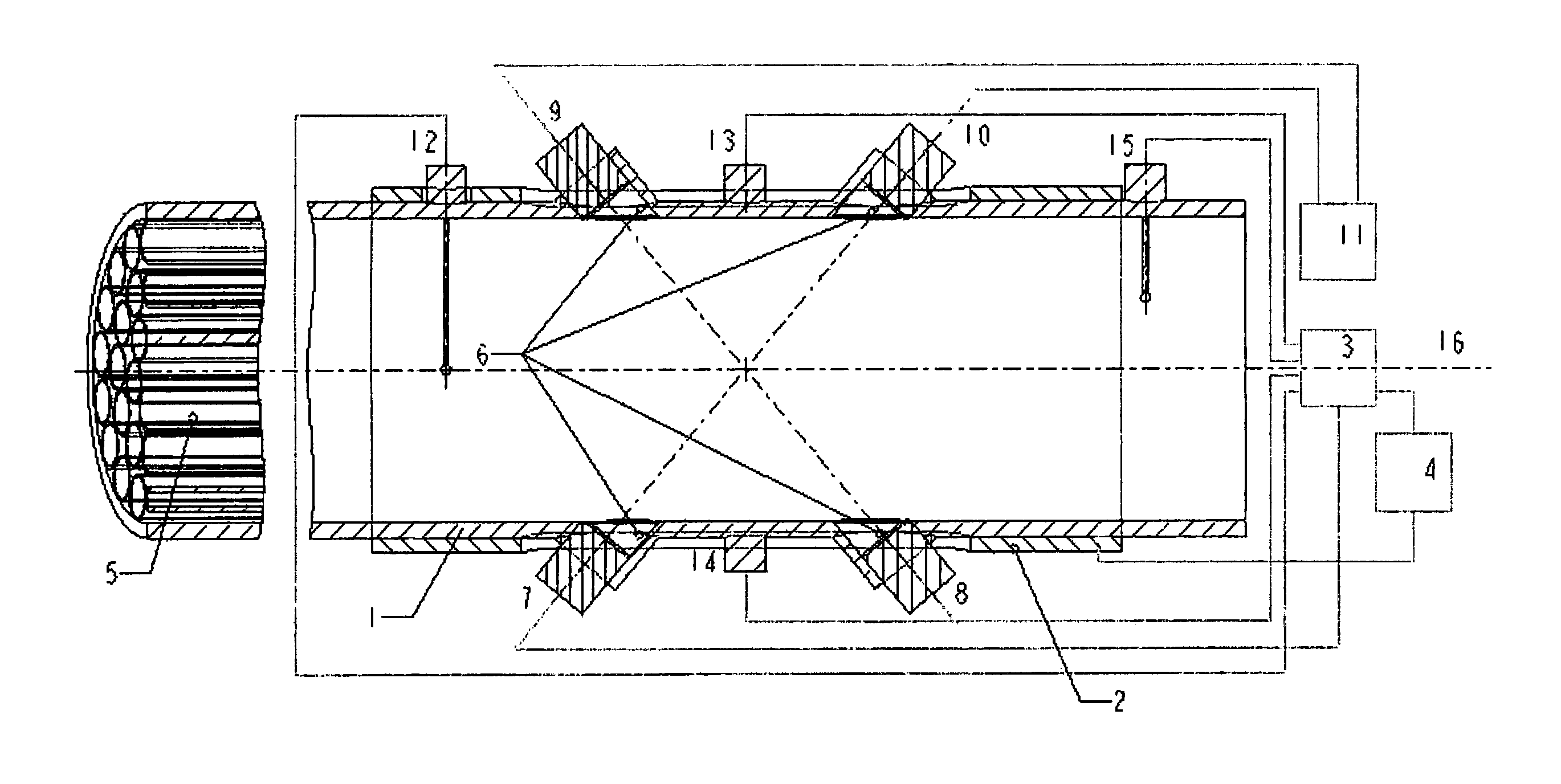
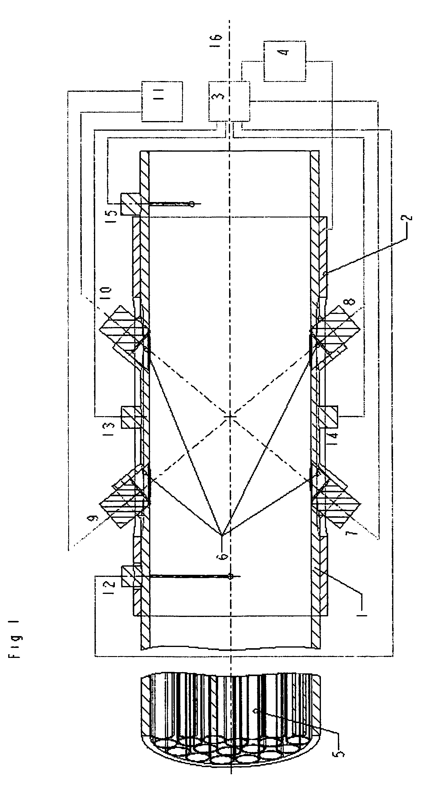
[0096]The longitudinal section of the inventive gas flowmeter arrangement of FIG. 1 shows the measuring pipe 1 through which the gas flows whose volume or mass it to be determined. The measuring pipe 1 is provided with a heating element 2 with which the temperature of the measuring pipe 1 can be increased and controlled via the evaluation electronics 3 while interconnected to heating control electronics 4. The measuring pipe is advantageously equipped with additional flow and temperature profile-forming baffles 5 in front of the location of the transit time measurement (relative to the direction of the main flow through the pipe.) These baffles 5 may be designed as guiding metal foils or bundles of tubing having a smaller diameter than the measuring pipe 1.

[0097]The transmission transducers 7 and 8 as well as the reception transducers 9 and 10 are inserted in the pockets or lateral cylindrical pieces of the measuring pipe, which can be closed off by the acoustically-transmissive ful...


PUM


Abstract

An ultrasonic gas flowmeter includes a measuring pipe with flowing gas, transmitting and receiving sound transducers, transmission and reception electronics, and evaluation electronics. The sound transducers (7, 8, 9, 10) are designed as capacitive electro-acoustic ultrasonic transducers to construct a flowmeter with improved capacity, especially in view of temperature stability and the reduction and consideration of a temperature profile. Devices (5, 6) are provided to level the gas temperature profile and to minimize the influence of the temperature profile on the flow measurement. A more accurate and dependable detection of the volume flow or the mass flow of gases is to be achieved, especially in highly dynamic flows, for the method of determining the flow of gases whereby the mean flow velocity is determined and the flowing gas quantity is determined with highly synchronized resolution from the two transit times of two acoustic signals. In addition, an assessed value is computed (35) for the flow after the determination of the transit times and the assessed value is corrected at least by means of a characteristic temperature of the gas and the temperature of the wall of the measuring pipe (36).

Description

BACKGROUND OF THE INVENTION[0001]1. Field of the Invention[0002]The invention relates to an ultrasonic gas flowmeter including at least one transmitting sound transducer, one receiving sound transducer, transmission and reception electronics, and a device to measure exhaust flows of internal combustion engines, as well as a method to determine the flow of gases whereby the mean flow velocity is determined and whereby the flowing quantity of gas is also determined with a highly synchronized resolution from the transit time of the acoustic signals between transmitter and receiver.[0003]2. The Prior Art[0004]Such ultrasonic flowmeters are known for fluids and gases and they are the subject of various publications and professional articles. They use the so-called dragging effect, namely in that the velocity in the direction of the beam of acoustic signals in fluids is not only determined by the orientation of the acoustic transmitter and the sound velocity of the (static) medium, but th...

Claims


Application Information

Patent Timeline
Patent Type & Authority Patents(United States)
IPC IPC(8): G01F1/66G01F1/00G01F15/02
CPCG01F1/662G01F15/024G01F1/668G01F1/667
Inventor KUPNIK, MARIOSCHRODER, ANDREASWIESINGER, MICHAELHARMS, KLAUS-CHRISTOPH
Owner AVL LIST GMBH
Why Eureka
Try Eureka