Method of and apparatus for forming timbers with rounded ends

a technology of rounded ends and forming methods, applied in the field of forming methods and apparatuses, to achieve the effects of low labor costs, high production rate, and low cos

Inactive Publication Date: 2006-08-22
MITEK HLDG INC
View PDF60 Cites 12 Cited by
  • Summary
  • Abstract
  • Description
  • Claims
  • Application Information

AI Technical Summary

Benefits of technology

[0003]Accordingly, among the several objects of the invention may be noted the provision of a method of and apparatus for forming timbers with rounded ends at a relatively high rate of production and at relatively low cost (low labor cost); the provision of such a method and apparatus for the automatic or semi-automatic production of the timbers with the rounded ends; the provision of such a method and apparatus for production of timbers of different lengths; and the provision of such a method and apparatus for reliable and economical rounded-end web production.

Problems solved by technology

This has entailed a great deal of sawing with the requirement for cutting at different angles and the problem of organizing the cut timbers according to the mitering angles.

Method used


Image

  • Method of and apparatus for forming timbers with rounded ends
  • Method of and apparatus for forming timbers with rounded ends
  • Method of and apparatus for forming timbers with rounded ends

Examples


Embodiment Construction

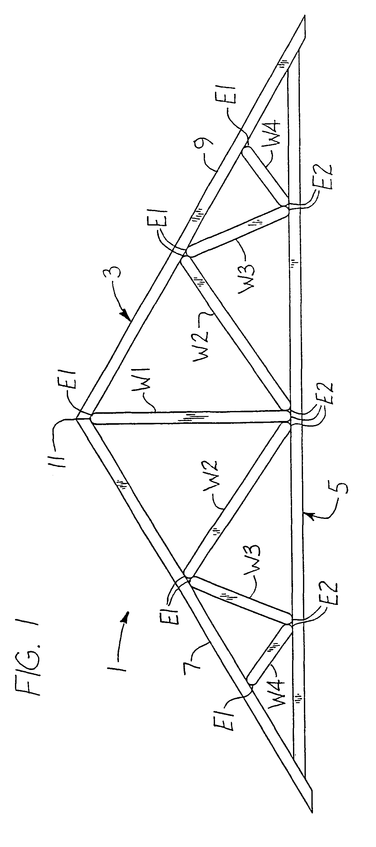
[0036]Referring first to FIG. 1 of the drawings, there is illustrated a timber truss I, more particularly a modified Queenpost truss, having an upper chord designated in its entirety by the reference numeral 3, a lower chord 5 and webs such as indicated at W1, W2, W3 triangulating the triangular space between the upper chord (comprising inclined timbers 7 and 9 meeting at peak 11) and the lower chord. The lower chord 5, each of the upper chord timbers 7, 9 and each of the webs is constituted, for example, by a length of 2×4 timber (the sides of which, as well understood, being somewhat minus 2″ and 4″ wide and hence identified as the 2″ and 4″ wide sides) the 4″-sides of the chords being vertical, the 4″-sides of the webs being in the vertical planes of the 4″-sides of the chords. As illustrated, each web has rounded ends E1, E2 (each of which is curved generally in a semi-circle from one 2″-side to the other of the respective 2×4in contact with a respective chord member at the resp...


PUM


Abstract

The method of forming timbers especially for use as webs in timber roof trusses comprising feeding timbers in a predetermined path with the timbers extending transversely to the direction of feed and, as the timbers are so fed, shaping the ends thereof to rounded form, and apparatus for carrying out said method comprising conveyors for feeding the work, a saw for cutting the timbers to length, and cutters for the end shaping.

Description

BACKGROUND OF THE INVENTION[0001]This invention relates to a method of and apparatus for forming timbers, for example, U.S. 2×4s, with rounded ends especially for use as web members (“webs”) for timber trusses, being particularly concerned with a method of and apparatus for cutting timbers to such length as may be called for, and cutting the ends of the sized (cut to length) timbers to rounded form.[0002]As is well known, timber roof trusses, such as Fink, Howe and Queenpost timber trusses, comprise upper and lower timber chords with timber web members extending therebetween triangulating the space between the chords, the chords and web members (which may be simply termed “webs”) being constituted for example by 2×4 timbers fastened together at the panel points (the points where the webs intersect the chords) by nailing plates for example. In much of the timber truss construction in the past, the webs have been fabricated with each end cut off straight at the requisite angle for eng...

Claims


Application Information

Patent Timeline
Patent Type & Authority Patents(United States)
IPC IPC(8): B27M3/08B27B31/00B27C5/06B65G19/00B27C5/00B27C5/08B27C9/04B27F5/02B27G19/10B27M1/08
CPCB27C5/00B27C5/08B27M1/08B27F5/026B27G19/10B27C9/04
Inventor KELLY, RODGER L.TOOMBS, IV, EUGENE
Owner MITEK HLDG INC
Why Eureka
Try Eureka