Flat heat exchanger plate and bulk material heat exchanger using the same

a heat exchanger and bulk material technology, applied in the field of flat heat exchanger plates, can solve the problems of reducing the heat exchange efficiency of the heat exchanger, reducing the flow of material through the heat exchanger, and ultimately losing production, so as to prevent the interior distance between the sides of the plates from increasing, less expensive, and less heavy duty

Active Publication Date: 2006-08-22
DAWSON & CO
View PDF17 Cites 47 Cited by
  • Summary
  • Abstract
  • Description
  • Claims
  • Application Information

AI Technical Summary

Benefits of technology

[0009]To withstand the negative pressure within the flat heat exchanger plate, pressure-resisting elements are positioned within the plate and may be unattached or secured to either or both internal surfaces of the sidewalls of the plate. The pressure resisting members or pressure resistor members prevent the sidewalls of the plate from deforming or collapsing inward due to the negative operating pressure present within the plate.
[0010]During initial filling of the flat heat exchanger plate with a heat exchange medium or during non-operational periods of the plates, the sides of the plate may tend to bow outward causing the plate to inflate due to the low positive pressure exerted by the heat exchange medium present within the plate in a static state. To prevent this from occurring, pressure restraint members are positioned within the plate and are secured to both sides of the plate, thereby preventing the interior distance between the sides of the plates from increasing.
[0011]Flow diverters are positioned within the flow passage of the flat heat exchanger plate and create flow channels for the heat exchange medium to follow. The flow diverters can be formed to any suitable shape from flat stock material or from solid or hollow sectional material and in some applications plastic mouldings could be employed. In addition, the flow diverters can also aid the pressure resistors in preventing the flat heat exchanger plate from collapsing due to internal negative pressures.
[0012]An additional advantage of operating the flat heat exchanger plate under negative pressure is the ability to use manifolds that are less expensive and less heavy duty than that of the manifolds required for heat exchanger plates that operate under positive pressure. A lighter duty and less costly manifold, typically a section of pipe or any hollow section material can be used.
[0013]In additional embodiments of the flat heat exchanger plate of the present invention, the plate is constructed with tapered sides, which is beneficial in the flow of fine particulate material. The increasing width of the material flow path due to the tapered design of the plate will reduce pressure build-up in the material, thereby making it less likely for particles to accumulate on the sides of the plate.

Problems solved by technology

In some circumstances, the material is allowed to collect to a point where the material will bridge between adjacent plates; this not only reduces the heat transfer efficiency of the heat exchanger, but also restricts the flow of the material through the heat exchanger.
These circumstances are very undesirable because the operation of heat exchanger must be shut down for a period of time to clean the plates, which many times means the material production line is also shut down, resulting in loss of production and ultimately loss in profits.

Method used


Image

  • Flat heat exchanger plate and bulk material heat exchanger using the same
  • Flat heat exchanger plate and bulk material heat exchanger using the same
  • Flat heat exchanger plate and bulk material heat exchanger using the same

Examples


third embodiment

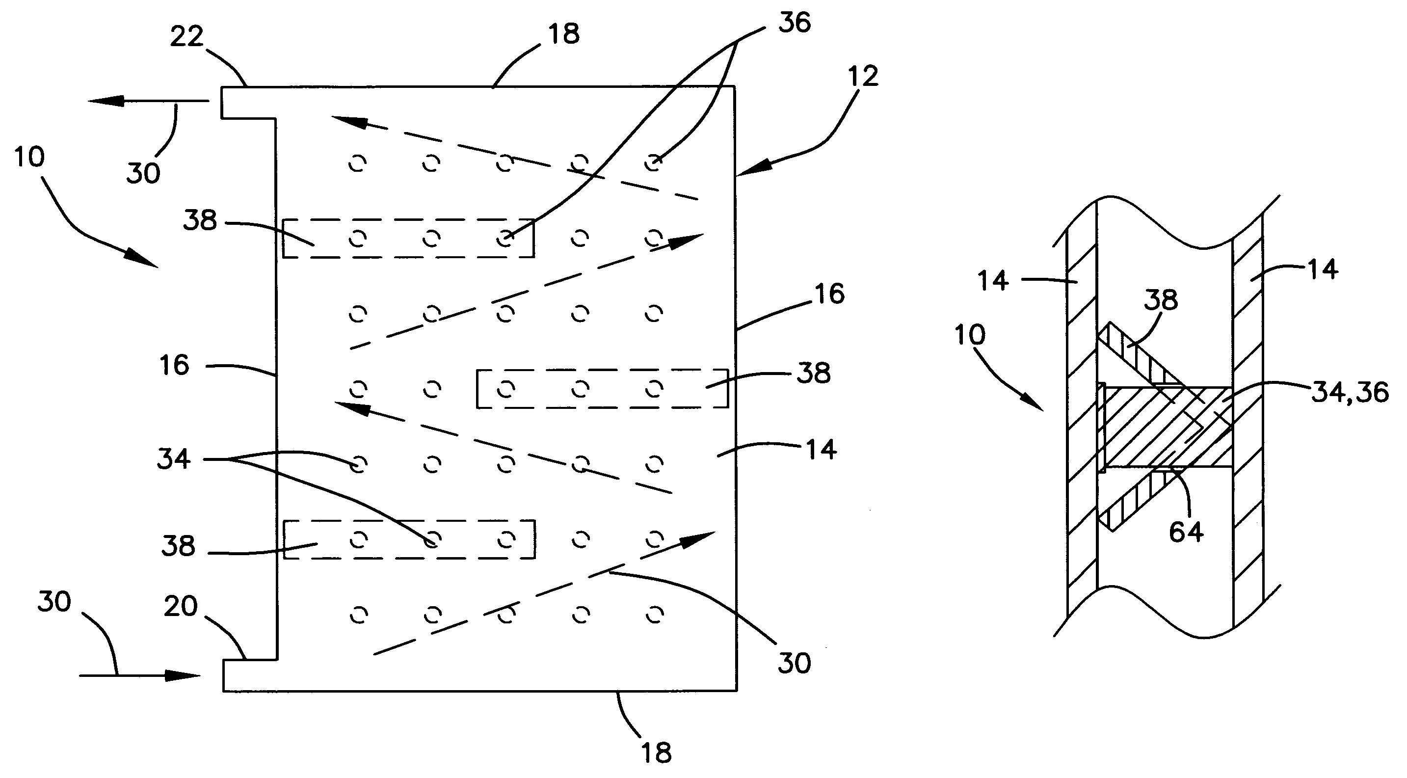
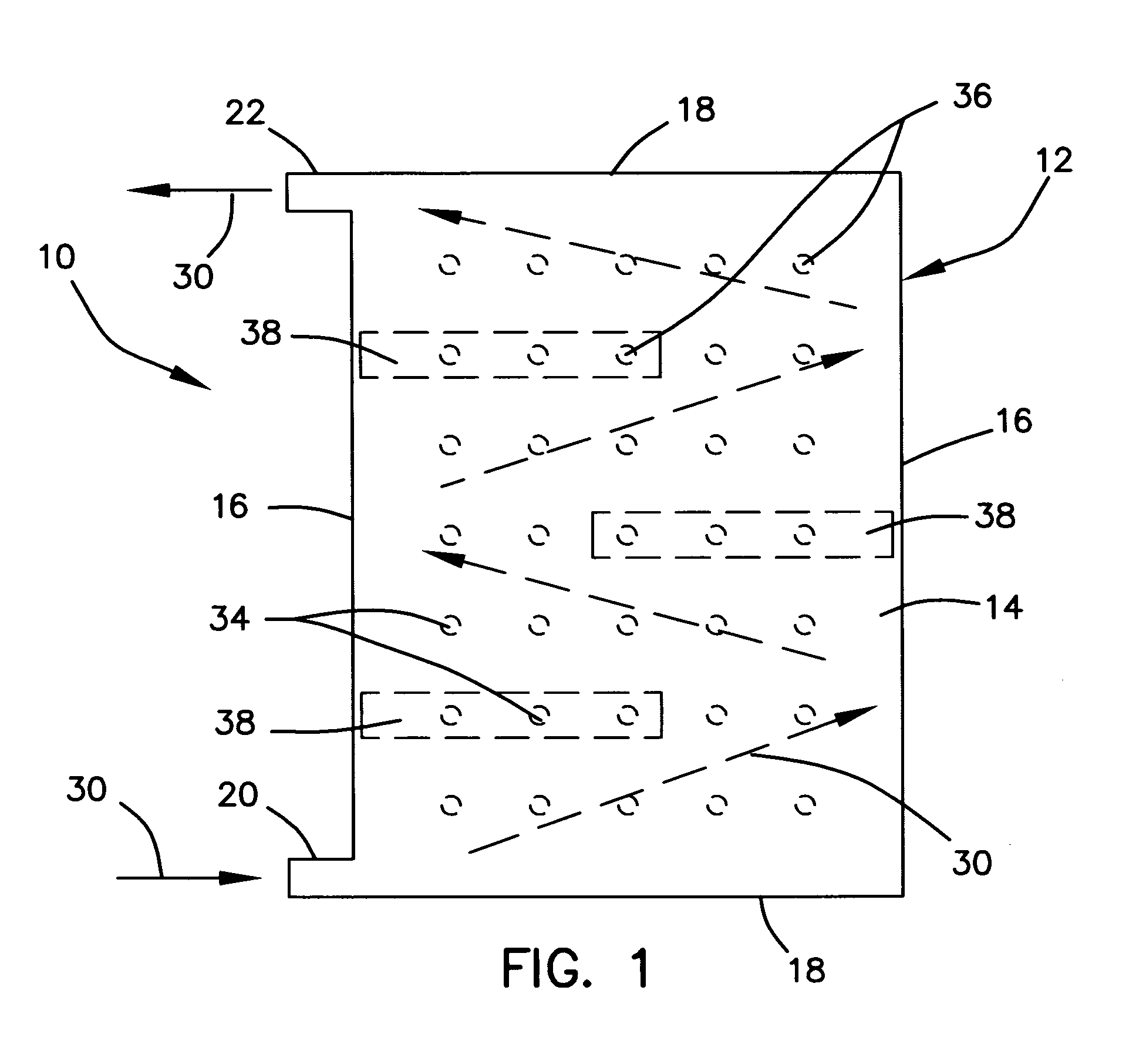
[0078]Referring now to FIGS. 11, 12 and 13, which illustrate the flat heat exchanger plate 10 of the present invention and an additional example of a flow diverter assembly 38 for use with a tapered or parallel plate. The flow diverter assembly 38 of this embodiment includes a plurality of tapered flow diverter strips 70 which are interlocked with a plurality of flow control strips 72. Preferably, the flow control strips 72 and the tapered flow diverter strips 70 are interlocked orthogonal to each other. The flow control strips 72 include a plurality of reduced sections 74, which are formed to be positioned between adjacent tapered flow diverter strips 70 and serve to control the amount of heat exchange medium that passes each flow control strip. The flow diverter 38 of this embodiment is also used to prevent the tapered plate 10 from collapsing under negative operating pressure. Pressure restraint members 36 (not illustrated) may also be used in the same manner as described previou...

fourth embodiment

[0079]Referring to FIGS. 13b and 13c, which illustrate the flat heat exchanger plate 10 of the present invention and an additional example of a plurality of flow diverters 38 for use with tapered or parallel flat heat exchanger plate. The flow diverter 38 of this example is a tapered or parallel strip of material formed in a serpentine shape and includes a heat exchange medium flow control leg 39. The flow control leg 39 restricts the flow of heat exchange medium into each chamber 41 to ensure an even flow rate of heat exchange medium within each chamber across the plate. The flow diverter 38 of this example is also used to prevent the plate 10 from collapsing under negative operating pressure. In addition to the flow diverters 38, pressure restraint members 36. not illustrated, can be used in the same manner as previously described to prevent inflation of the plate 10 and to aid in the positioning of the flow diverters 38 within the plate.

[0080]Turning to FIGS. 14 and 15 a fifth me...


PUM


Abstract

A flat heat exchanger plate typically used in a bulk material heat exchanger is provided. The flat heat exchanger plate is designed to operate under a negative internal pressure to eliminate depressions or dimples that are typically formed into the sides of these types of heat exchanger coils during the manufacture process. With the removal of the depressions or dimples the tendency for bulk material to accumulate to the exterior surface of the plate is reduced, thereby increasing the service period of the plate.

Description

BACKGROUND OF THE INVENTION[0001]1. Field of the Invention[0002]The present invention relates generally to flat heat exchanger plates for use in heat exchangers. More particularly, relating to flat heat exchanger plates used in bulk material type heat exchangers.[0003]2. Description of the Prior Art[0004]Typically, in processing bulk materials, such as pellets, granules, powders or the like, heat exchangers are employed to either cool or heat the material during the processing thereof. The heat exchangers employed consist of an array of heat exchanger plates arranged side-by-side in spaced relationship and are positioned in an open top and open bottom housing. The like ends of each heat exchanger plate are connected to together by means of a manifold and a heat exchange medium, such as water, oil, glycol or the like is caused to flow through the plates. Generally, the material treated by the heat exchanger is allowed to gravity flow through the housing and the spaces between the spa...

Claims


Application Information

Patent Timeline
Patent Type & Authority Patents(United States)
IPC IPC(8): F28F3/02F26B17/10F28D9/00F28G7/00
CPCF28D9/0031F28D9/0068F28G7/00F28F2225/04F28D2021/0045F28F2250/102
Inventor DAWSON, PETER
Owner DAWSON & CO
Why Eureka
Try Eureka