Skeleton equalizing antenna, RFID tag and RFID system using the same

a technology of equalizing antenna and rfid tag, which is applied in the direction of resonant antenna, burglar alarm mechanical actuation, instruments, etc., can solve the problems of conversion loss inevitably occurring in reality, low tolerance to various disturbance factors, and remarkably reduced electric power, so as to maintain visible light transmissivity

Inactive Publication Date: 2008-10-30
HITACHI LTD
View PDF0 Cites 12 Cited by
  • Summary
  • Abstract
  • Description
  • Claims
  • Application Information

AI Technical Summary

Benefits of technology

[0015]According to the present invention, it is possible to realize a circularly polarized antenna of a planar structure or an antenna which has an equalizing function to intentionally distort a frequency characteristic of the electromagnetic wave sent and received through the antenna while sufficiently maintaining visible-light transmissivity. Thus, the antenna has been realized without causing deterioration in aesthetic terms and covering meaningful symbols.

Problems solved by technology

Therefore, if the transmission distance becomes longer, when the electromagnetic wave emitted from the base station arrives at the base station again, its electric power is decreased remarkably, and its tolerance to various disturbance factors becomes very low.
In this regard, a conversion loss inevitably takes place in reality.

Method used


Image

  • Skeleton equalizing antenna, RFID tag and RFID system using the same
  • Skeleton equalizing antenna, RFID tag and RFID system using the same
  • Skeleton equalizing antenna, RFID tag and RFID system using the same

Examples


embodiment 1

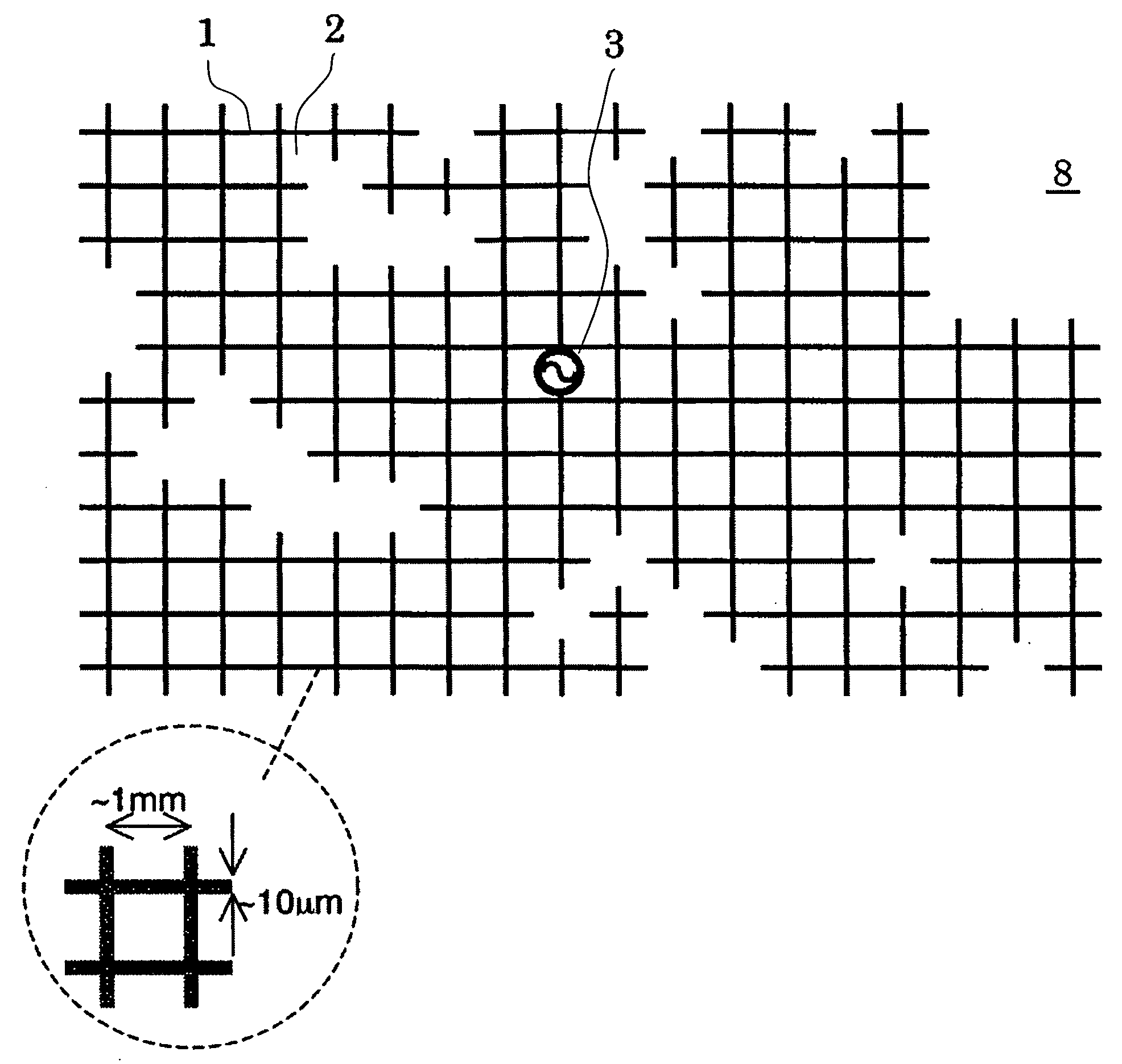
[0030]Now, an embodiment of the present invention will be described with reference to FIG. 1. FIG. 1 shows a structure of a skeleton equalizing antenna according to the embodiment of the present invention. In the skeleton equalizing antenna 8, a grid with different roughness and fineness provided around a feeding point 3 has a planar structure including linear conductors 1 and spacing 2 between the linear conductors.

[0031]That is, the antenna 8 of the present embodiment is composed of a planar structure including the conductive grid which has roughness and fineness around the feeding point 3. The frequency spectrum viewed from the feeding point 3 of the antenna has two or more stationary points. In other words, in plural frequencies, the antenna 8 of the present embodiment has a structure which satisfies a desired feeding-point impedance matching condition.

[0032]In the planar structure of the antenna 8 of the present embodiment, a ratio of a width for constituting the conductor grid...

embodiment 2

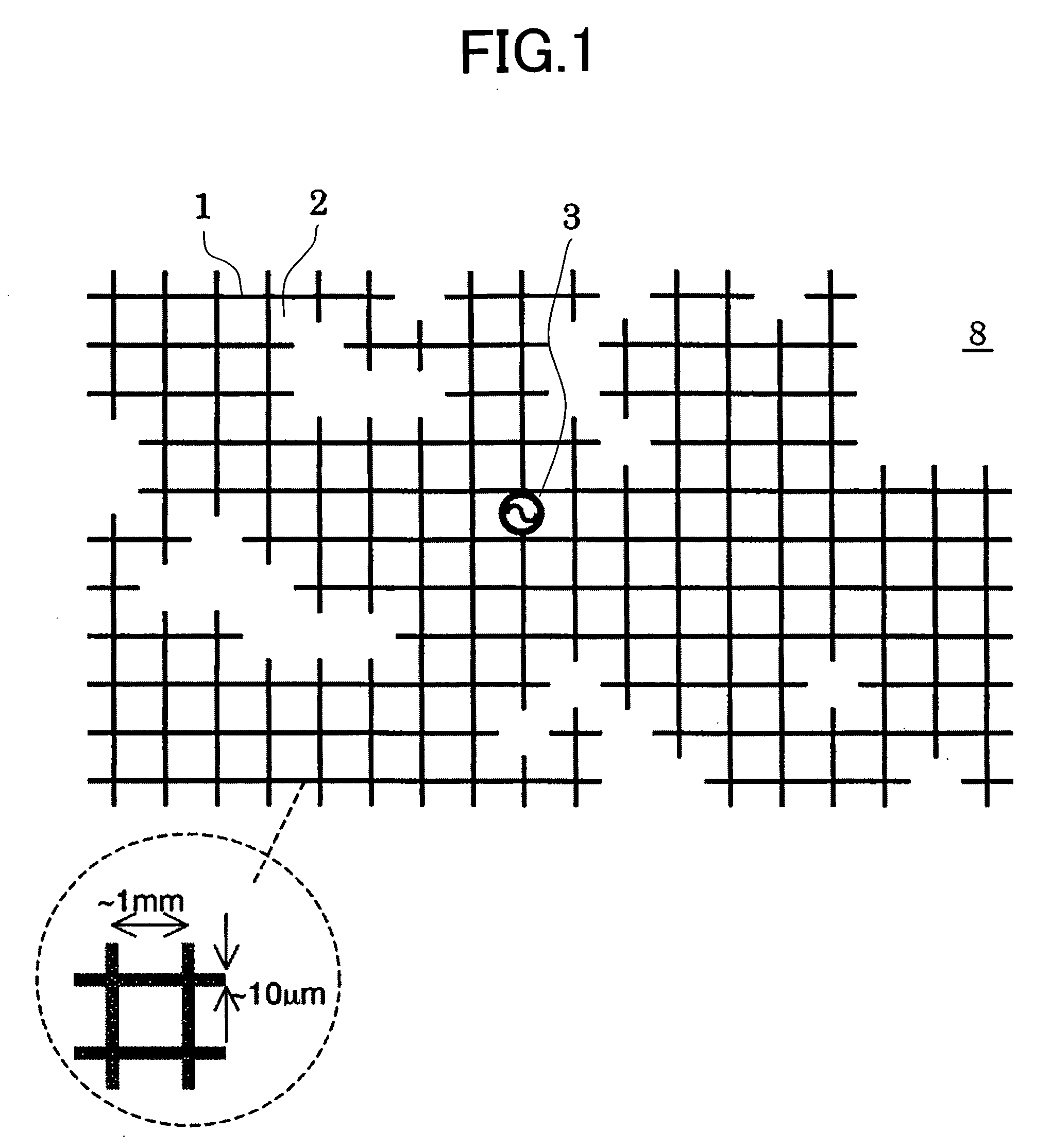
[0036]Referring to FIGS. 2 and 3, another embodiment of the present invention will be described. FIG. 2 shows a structure of an RFID tag using a skeleton equalizing antenna of the present invention. The structure is such that a high-frequency input / output point of the RFID chip 4 is connected to a feeding part 3 of the skeleton equalizing antenna 8. An example of a circuit diagram of the RFID chip 4 is shown in FIG. 3. The energy of electromagnetic waves transmitted from a base station through a skeleton equalizing antenna 41 is taken in, and is converted to a direct-current power supply in a rectifier circuit 42. A microprocessor 43 operated by the direct-current power supply drives a modulation circuit 44, modulation is applied on load impedance of the antenna 41, and the electromagnetic wave in which an amplitude of the received wave is modulated is emitted from the antenna 41.

[0037]According to the present embodiment, a circularly polarized antenna of a planar structure can be r...

embodiment 3

[0038]With reference to FIG. 4, another embodiment of the present invention will be described. FIG. 4 shows a configuration of another embodiment of the RFID tag using the skeleton equalizing antenna of the present invention. The present embodiment differs from the embodiment of FIG. 2 in that, besides the RFID chip 4, an electronic circuit 5 is provided inside the skeleton equalizing antenna. In general, the RFID chip includes an analog circuit and a digital circuit, and a high-frequency part of the analog circuit has a circuit which depends on a frequency in which the RFID tag operates. Since the circuit uses undulations peculiar to electromagnetic waves, there arises a need to use a transmission line, an inductive element, and a large capacity element. As a result, it is difficult to provide such a circuit inside the RFID which is physically restricted to a small region. These elements are replaced with circuitry using an electronic circuit in a conventional technology. However, ...


PUM


Abstract

The problems to be solved by the present invention are to provide an antenna which is applied to a wireless identification system wherein there is a long distance between a device to execute identification and a device attached to an object to be identified and which does not cause deterioration in aesthetic terms and covering of a meaningful symbol, and further to provide a wireless system using the antenna. According to the present invention, there are provided an antenna having a circularly polarizing function and a frequency equalizing function achieved by a grid structure having roughness and fineness around a feeding point and density which allows visible light to pass through, an RFID tag using the antenna, and an RFID system using the tag.

Description

CLAIM OF PRIORITY[0001]The present application claims priority from Japanese application JP2007-119413 filed on Apr. 27, 2007, the content of which is hereby incorporated by reference into this application.FIELD OF THE INVENTION[0002]The present invention relates to a skeleton equalizing antenna, and an RFID tag and an RFID system using the same. In particular, it relates to an antenna used for a case where there is a long distance between a base station and a terminal and to a wireless system including the base station provided with the antenna and the terminal.BACKGROUND OF THE INVENTION[0003]In a system where a scattered wave is used as a direct carrier wave between a base station and a terminal, there is known a conventional technology, which may also be called a “Direction Divide Duplex (DDD).” In this technology, by using a difference in directionality between an electromagnetic wave leaving the base station and an electromagnetic wave entering the base station, with use of a ...

Claims


Application Information

Patent Timeline
Patent Type & Authority Applications(United States)
IPC IPC(8): H01Q9/04G08B13/14
CPCH01Q1/2208H01Q1/38H01Q1/44H01Q9/04H01Q9/0407
Inventor TAKEI, KEN
Owner HITACHI LTD
Why Eureka
Try Eureka