Fitting for a liquid-tight cable leadthrough

a technology of liquid-tight cable and leadthrough, which is applied in the direction of cable termination, insulating body, manufacturing tools, etc., to achieve the effects of reducing thickness, simple installation, and uniform transmission of for

Active Publication Date: 2006-08-22
AIRBUS OPERATIONS GMBH
View PDF17 Cites 9 Cited by
  • Summary
  • Abstract
  • Description
  • Claims
  • Application Information

AI Technical Summary

Benefits of technology

[0011]According to an exemplary embodiment a cable leadthrough that fulfills the initially described requirements may be realized with a fitting according to the invention for liquid-tight cable leadthroughs in solid surfaces, which solid surfaces can be gripped from the back (“hintergreifbare feste Fläche”). The fitting according to this exemplary embodiment may comprisea moulded element (“Formkörper”) of an elastic material that at least almost completely fills out the opening in the solid surface provided for installing the respective cable, for example, a bore in the floor of an on-board kitchen. Openings for accommodating the cables may lead through the elastic moulded part. The elastic moulded part may have a cross section that approximately corresponds to the shape of the opening for installing the cable leadthrough. A particularly simple installation may be achieved if the cross section of the elastic moulded part is chosen such that a slight clearance for the installation of the cable leadthrough remains between the part of the moulded element situated in the opening and the wall of the opening. On its front faces, the elastic mounded element may be bordered by two solid plates. An upper end plate may completely cover the opening for the installation of the cable leadthrough and may have such dimensions that it can be supported on the edge of the opening. A lower end plate may have a cross section that is slightly smaller than the opening in the solid surface. This may make it possible that the lower end plate is moved into the opening when the elastic moulded element is deformed. It may be particularly advantageous to rigidly connect the end plates to the elastic moulded part.
[0012]A locking plate situated in front of the lower end plate may be connected to the upper end plate with the aid of a clamping element. One further exemplary embodiment of such clamping element comprises at least one screw that extends through the end plates, the elastic moulded element and the locking plate. The spacing between the upper end plate and the locking plate may be varied by tightening the screw. Thereby, the lower end plate may act as a spacer between the locking plate and the elastic moulded element which spacer needs to ensure the most uniform transmission of force possible into the elastic moulded element. As the spacing between the upper end plate and the locking plate may be reduced, the elastic moulded element may be compressed whereby its thickness may decrease and its cross section may increase. This may cause the underside of the elastic moulded element to be firmly pressed against the wall of the leadthrough opening. At the same time a pressure may be generated in the interior of the elastic moulded element which pressure may ensure a firm contact between the elastic moulded element and the cables leading through the elastic moulded element, as well as the clamping element, if applicable. Due to these measures, the elastic moulded element may produce an excellent seal relative to fluids butting against the cable leadthrough. The contact pressure producing the desired sealing effect may be easily adapted to the respective circumstances by choosing the relative change in thickness as well as the modulus of elasticity of the material for the elastic moulded element accordingly.
[0013]The locking plate may have such dimensions that it can be easily inserted through the cable leadthrough opening. Pivotable locking elements may be arranged on its outer edges. These locking elements may be pivoted between at least two positions, wherein one position may lead to a positioning of the pivotable locking elements, which positioning does not obstruct the insertion of the locking plate through the cable leadthrough opening, and wherein the other position of the locking elements may be defined by a limit stop in such a way that the pivotable locking elements may grip the solid surface, containing the cable leadthrough opening, from the back. Consequently, an end stop that limits the deformation of the elastic moulded element may be realized when the clamping element may be tightened and the spacing between the locking plate and the upper end plate may be correspondingly reduced. This may securely obviates that a to high contact pressure relative to the lead-through cable may accidentally set, which may contribute to the increase of the installation security. In case that the clamping element provided may be tightened more than it is designed for reaching of the maximum deformation of the elastic moulded element additionally generated forces may be directly transmitted into the solid surface containing the cable leadthrough opening via the upper end plate and the pivoted locking elements that may be situated in the stopping position. This may make it possible to fix the entire fitting in the leadthrough opening much more solidly than it would be possible by utilizing a contact pressure that can be withstood by the lead-through cables.
[0015]The fitting for the cable leadthrough may be mounted in the leadthrough opening, wherein an combination of a non-positive and a positive mounting principle may be employed. The stability of the non-positive connection may be defined by the modulus of elasticity and the geometry of the elastic moulded element in relation to the opening for the installation of the cable leadthrough, as well as the position of the limit stop formed by the pivoted locking elements. Clamping forces higher than those required for reaching the limit stop of the locking plate may result in a high positional stability of the fitting according to the invention, which fitting may be additionally secured from falling out of the leadthrough opening by a positive connection. Due to these measures, the positional stability of the fitting may be obtainable which stability may be substantially limited only by the resistance to fracture of the pivoted locking elements and their mounting on the locking plate. Thus, the cable leadthrough may be able to withstand high forces and, due to its construction, simultaneously may shield the region in which the cable may be actually fixed from external influences such as, for example, falling objects or other shocks that could impair the sealing effect.

Problems solved by technology

This may cause the underside of the elastic moulded element to be firmly pressed against the wall of the leadthrough opening.

Method used


Image

  • Fitting for a liquid-tight cable leadthrough
  • Fitting for a liquid-tight cable leadthrough
  • Fitting for a liquid-tight cable leadthrough

Examples


Embodiment Construction

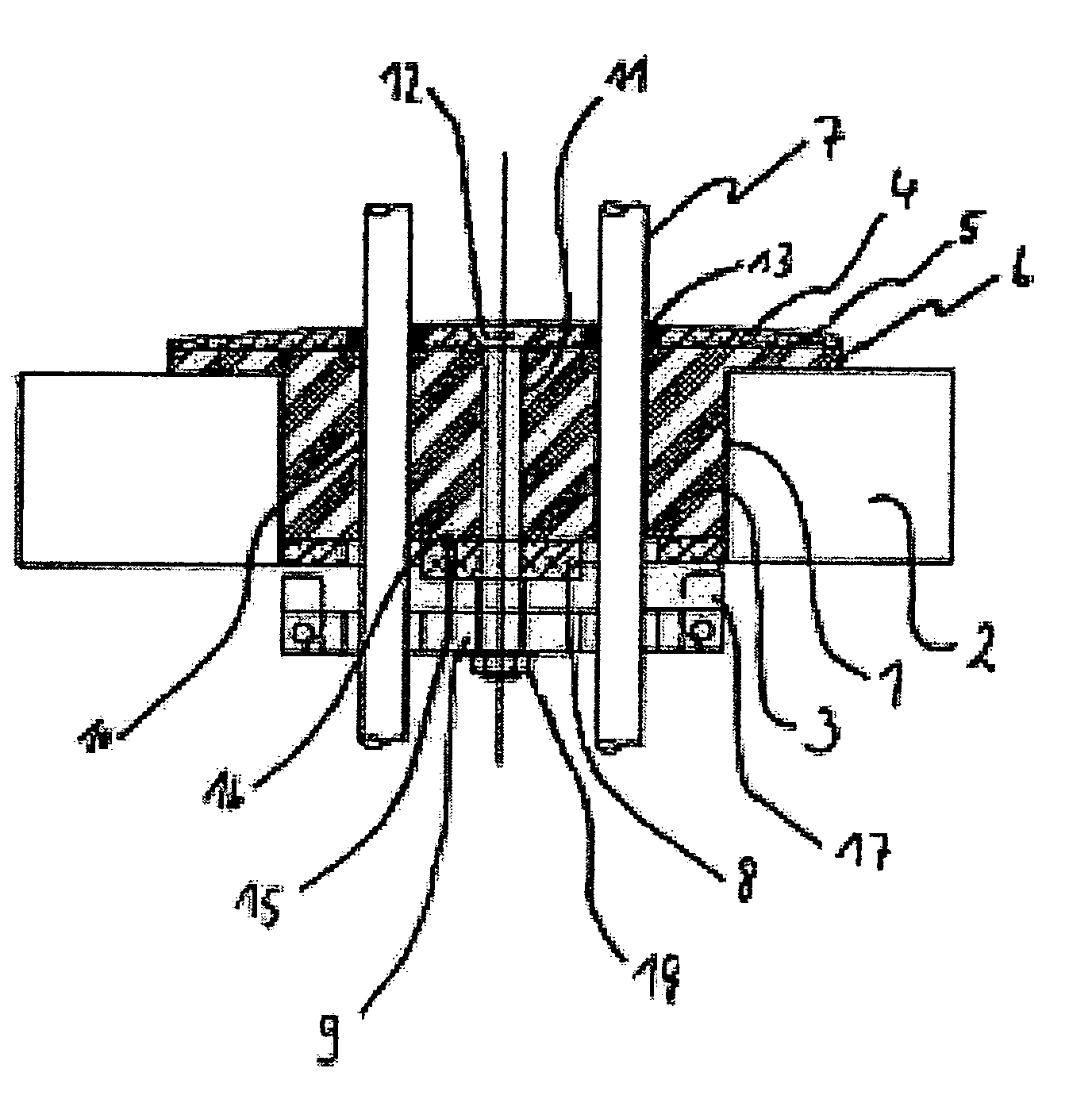
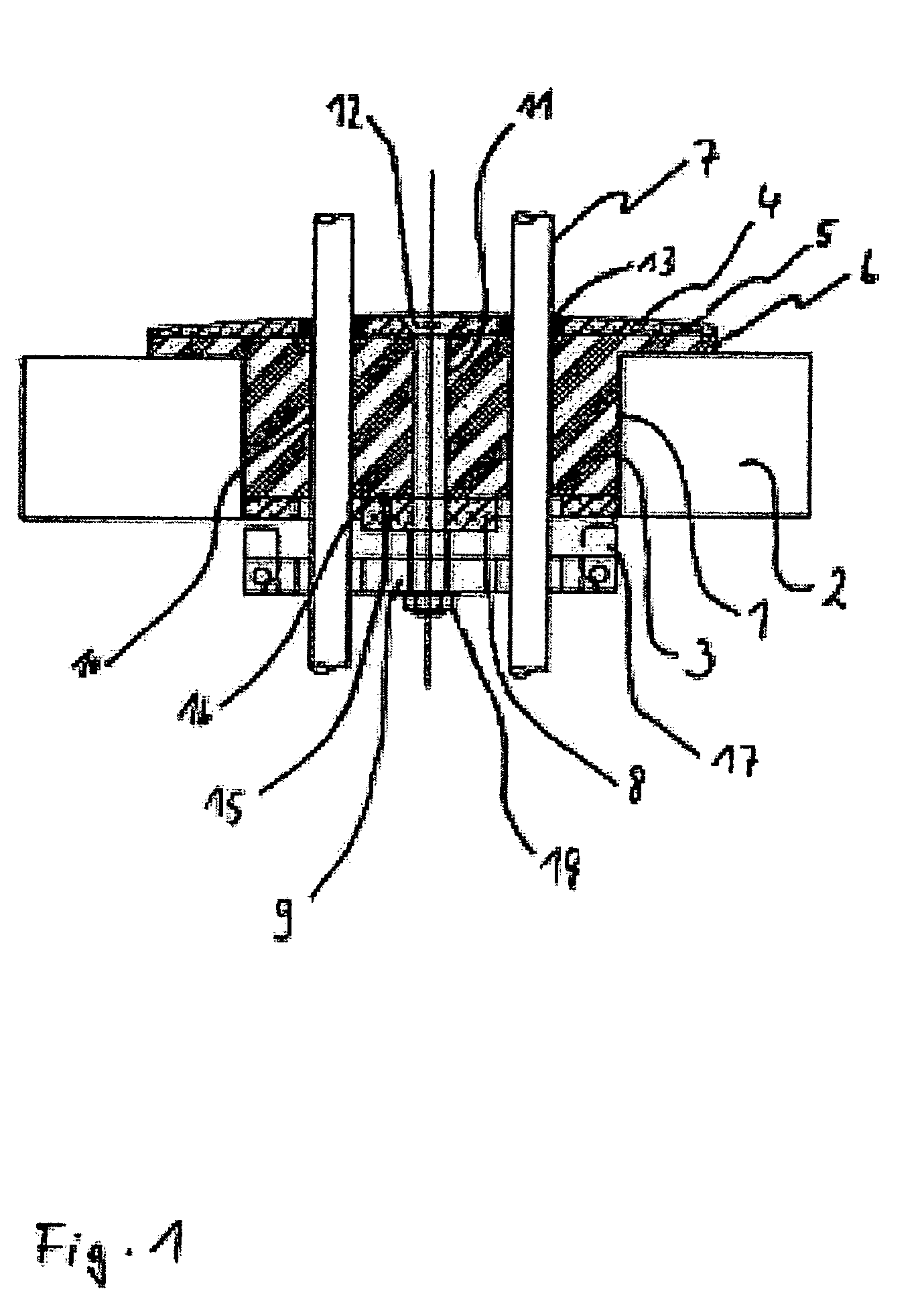
[0019]FIG. 1 shows an uninstalled fitting according to the invention that, which is completely inserted into an opening 1 for installing a cable leadthrough in a solid surface 2, which solid surface can be gripped from the back. The opening 1 is realized in the form of a bore in the floor of an on-board kitchen in an aircraft. A largely cylindrical rubber block 3, as an elastic moulded element, is connected with a circular upper boundary plate 4 by vulcanization. The diameter of the section of the rubber block 3 that extends into the bore 1 in the floor of the kitchen is slightly smaller than the diameter of the opening 1. The upper boundary plate 4 has a diameter that is significantly larger than the leadthrough opening 1. Consequently, the edge region of the circular upper boundary plate 4 forms a peripheral support region 5, in which the upper boundary plate 4 can be pressed against the floor. In the contact region with the upper boundary plate 4, the rubber block 3 contains a wi...


PUM


Abstract

The invention relates to a fitting for a liquid-tight cable leadthrough in an opening (1) in a solid surface (2), which solid surface can be gripped from the back, wherein said fitting comprises an upper boundary plate (4) that covers the opening (1), an elastic moulded element (3) that flatly contacts and is connected to the upper boundary plate (4) and can be at least partially inserted into the opening (1), a lower boundary plate (8) that can be lead through the opening (1), wherein the lower boundary plate flatly contacts and is connected to the elastic moulded element (3) on the opposite side of the elastic moulded element (3) referred to the upper boundary plate (4), a locking plate (9) that can be moved relative to the lower boundary plate (8) and is providable with at least two pivoted locking elements (17), wherein said locking elements are supported between pairs of mounting limbs (20) by element of a bolt (22) and can be pivoted between a position in which the locking plate (9) can be lead through the opening (1) and a stopping position which they enables a gripping from the back of the solid surface (2), at least one clamping element for adjusting the spacing between the upper boundary plate (4) and the locking plate (9) against forces generated during a deformation of the elastic moulded element, and opening (10) that extends through the locking plate (9), the boundary plates (4, 8) and the elastic moulded element (3) and serves for accommodating a cable (7) to be lead through the solid surface (2).

Description

REFERENCE TO RELATED APPLICATIONS[0001]This application claims the benefit of the filing date of U.S. Provisional Patent Application No. 60 / 602,700 filed Aug. 19, 2004, and of the German Patent Application No. 10 2004 040 293.0 filed Aug. 19, 2004 the disclosures of which are hereby incorporated herein by reference.FIELD OF THE INVENTION[0002]The invention relates to a fitting for a liquid-tight cable leadthrough in solid surfaces, which solid surface can be gripped from the back. In this context, the term solid surfaces refers, among other things, to various self-supporting wall structures, ceiling structures or floor structures, as well as other partitioning elements and boundary elements. The fittings according to the invention can be advantageously utilized in all instances, in which a cable leadthrough needs to be quickly installed and a sufficient sealing effect as well as an adequate strain relief needs to be ensured.TECHNOLOGICAL BACKGROUND[0003]Fittings of this type are use...

Claims


Application Information

Patent Timeline
Patent Type & Authority Patents(United States)
IPC IPC(8): H02G15/04F16L5/02
CPCH02G3/088H02G15/013H02G3/22Y10T16/063
Inventor MOTZIGKEIT, DANIEL
Owner AIRBUS OPERATIONS GMBH
Why Eureka
Try Eureka