Apparatus for data input and key detection method thereof

a data input and data technology, applied in the field of data input apparatus, can solve the problems of exhausting controller resources, complex monitoring of keys in matrixes, and more complicated monitoring of keys being directly connected, so as to reduce the required number of gpio pins, resource and power consumption, and the complexity of the operation of the controller

Active Publication Date: 2006-08-22
HTC CORP
View PDF3 Cites 13 Cited by
  • Summary
  • Abstract
  • Description
  • Claims
  • Application Information

AI Technical Summary

Benefits of technology

[0009]The object of the present invention is to provide an apparatus for data input and a key detection method thereof which

Problems solved by technology

Since the GPIO pin number is limited and it is impossible to dedicate all of GPIO pins to the connections of the keypad or keyboard, this configuration only applies to a keypad or keyboard with a small number of keys.
Moreover, the controller may not have a pin for interruption, which results in a need for periodical monitoring of the keys and may exhaust the controller resource.
The monitoring of keys in a matrix is more complicated than that of

Method used


Image

  • Apparatus for data input and key detection method thereof
  • Apparatus for data input and key detection method thereof
  • Apparatus for data input and key detection method thereof

Examples


first embodiment

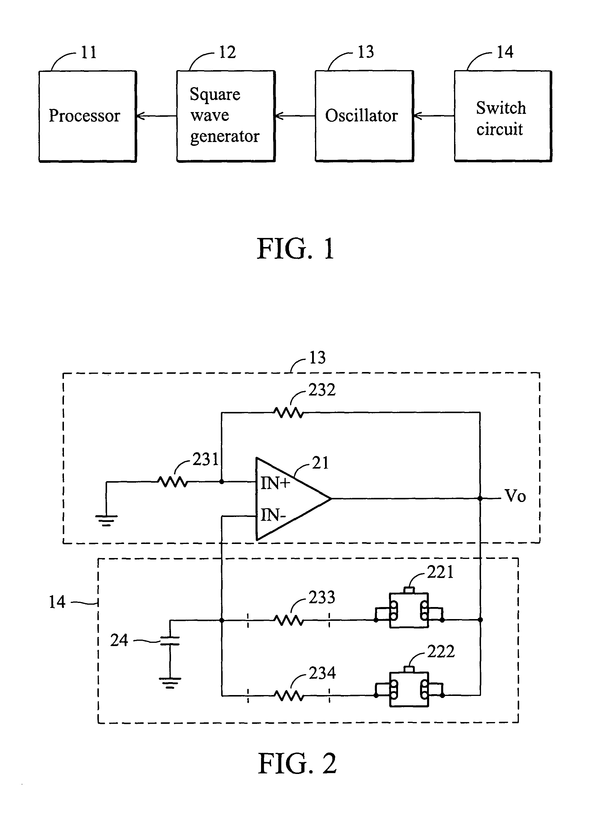
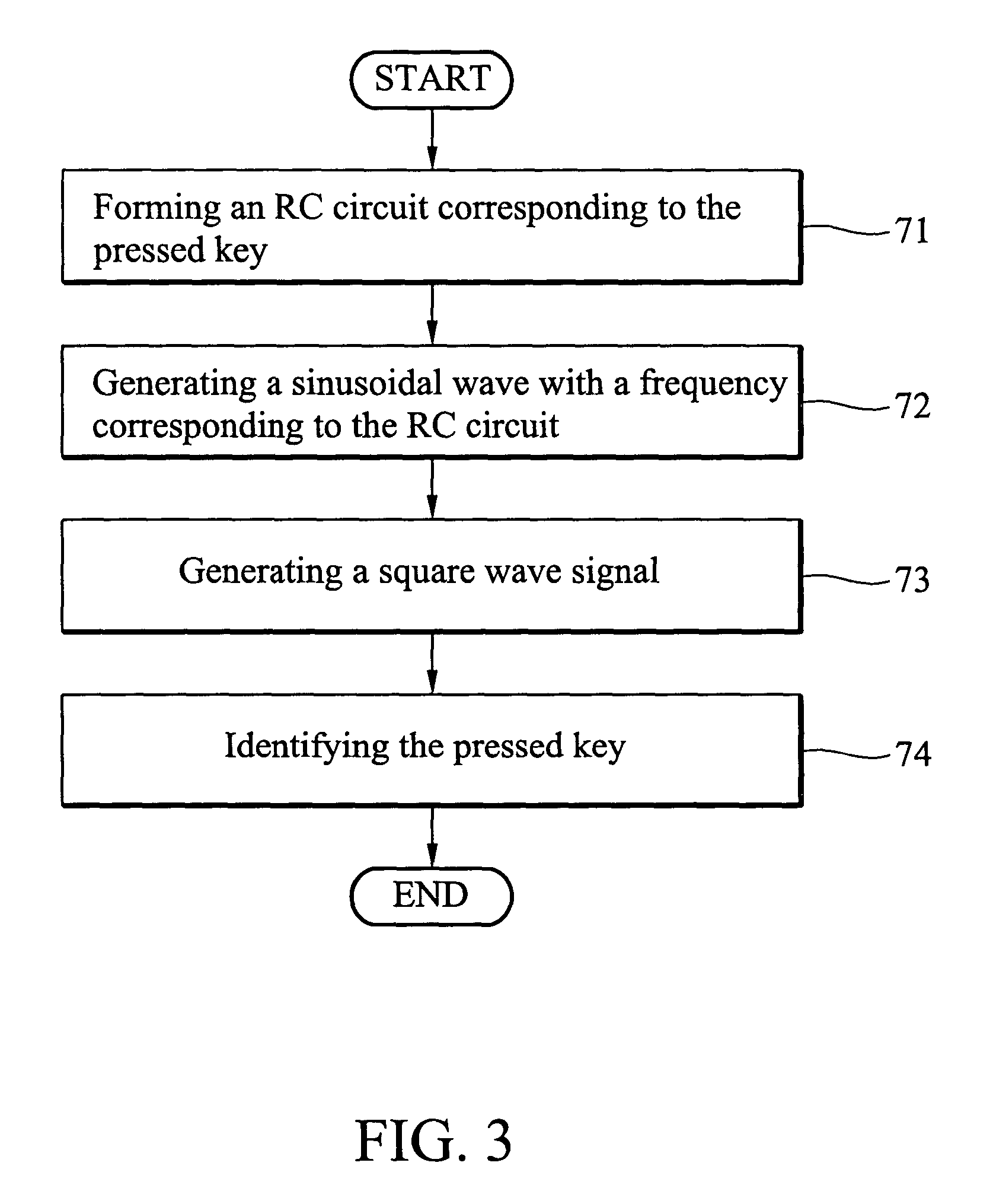
[0023]FIG. 1 is a diagram showing an apparatus for data input according to the invention. It includes a processor 11, square wave generator 12, oscillator 13 and switch circuit 14. The switch circuit 14 has keys (not shown) and forms an equivalent RC circuit with an RC constant selected by the key being pressed. The oscillator 13 generates a sinusoidal wave signal with a frequency corresponding to the RC constant of the equivalent RC circuit formed by the switch circuit 14. The square wave generator 12 transforms the sinusoidal wave signal to a square wave signal with the same frequency. The processor 11 receives the square wave signal to identify the pressed key by the frequency thereof.

[0024]FIG. 2 is a diagram showing the oscillator 13 and switch circuit 14 of the apparatus for data input according to the first embodiment of the invention. The keys are implemented by switches 221 and 222 (only two switches are illustrated for example). The switch circuit 14 further includes a cap...

second embodiment

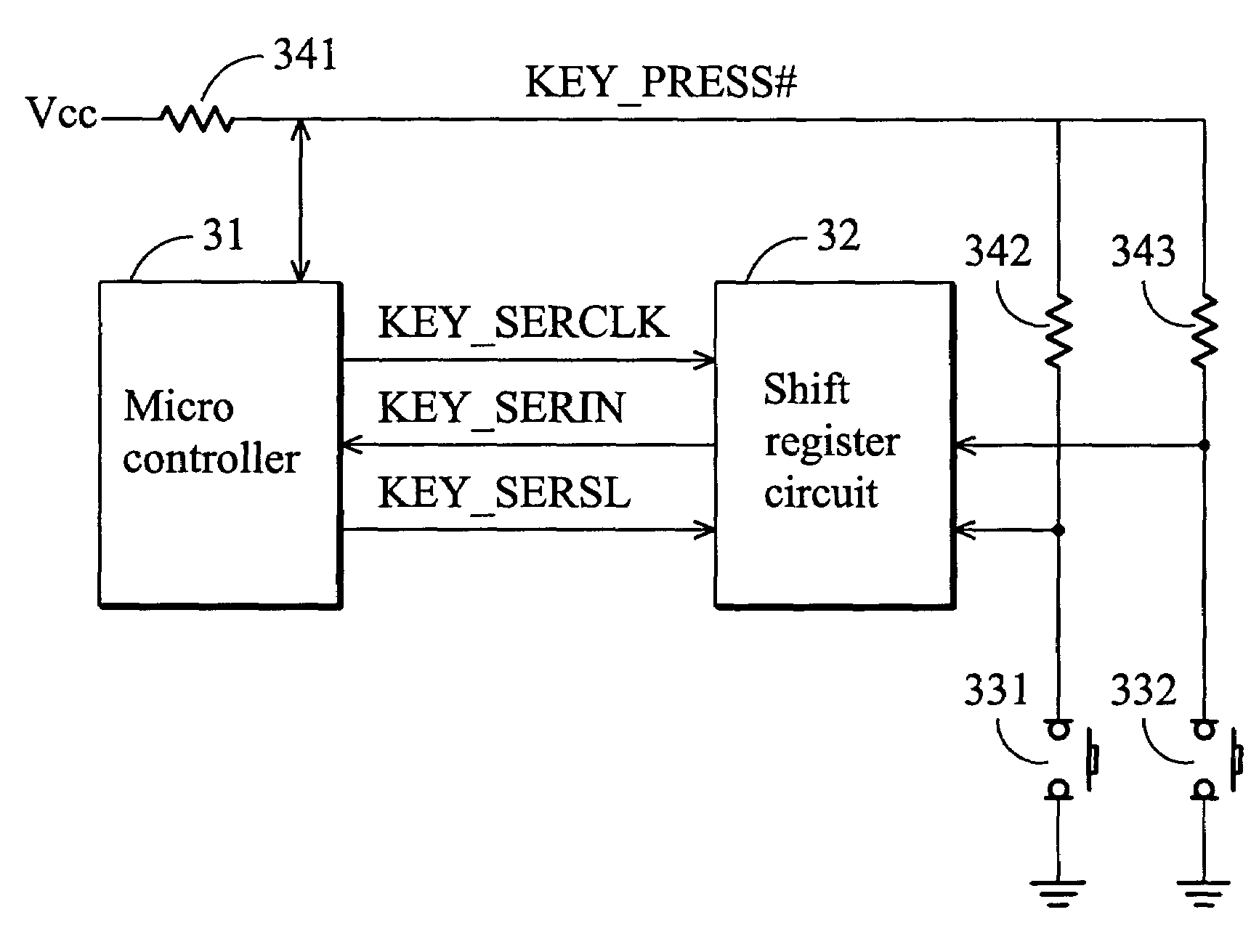
[0032]FIG. 4 is a diagram showing an apparatus for data input according to the invention. It includes a sensing circuit composed of keys 331 and 332 (only two keys are illustrated for examples), and resistors 341, 342 and 343, a shift register circuit 32 and a microcontroller 31. The keys 331 and 332 are implemented by switches. The resistors 342 and 343 have first ends respectively coupled to the first ends of the switches 331 and 332 while the resistor 341 has a first end coupled to receive a power supply voltage Vcc and a second end coupled to both of the second ends of the resistors 342 and 343. The second ends of the switches 331 and 332 are commonly coupled to the ground.

[0033]The sensing circuit outputs an interruption signal KEY_PRESS# which is asserted by being pulled down to a low logic voltage level (as shown in FIG. 5A) when any one of the keys 331 and 332 is pressed. The sensing circuit also outputs a group of data bits identifying the pressed key. For example, a group ...


PUM


Abstract

An apparatus for data input. The apparatus comprises a sensing circuit for a plurality of keys, outputting an interruption signal and a corresponding group of data bits when one of the keys is pressed, a shift register circuit receiving a strobe signal, a clock signal and the group of data bits in parallel from the sensing circuit when the strobe signal is asserted, and serially outputting the group of data bits in synchronization with the clock signal, and a microcontroller receiving the interruption signal, outputting the strobe signal and clock signal when the interruption signal is asserted, and serially receiving the group of data bits from the shift register circuit to identify the key being pressed.

Description

[0001]This nonprovisional application claims priority under 35 U.S.C. § 119(a) on patent application Ser. No(s). 091125206 filed in TAIWAN, R.O.C. on Oct. 25, 2002, which is(are) herein incorporated by reference.BACKGROUND OF THE INVENION[0002]1. Field of the Invention[0003]The present invention relates to an apparatus for data input and particularly to a keypad or keyboard circuit, and key detection method thereof which achieves low power and system resource consumption.[0004]2. Description of the Prior Art[0005]Generally, there are two configurations of connection of the keypad or keyboard to the host.[0006]One is to connect each of the keys to one of the GPIO (General Purpose Input and Output) pins of a controller in the host. The controller of the host is the only device to detect and identify the keys. This configuration is characterized by its simplicity. However, the controller must have enough GPIO pins to afford such connections and the required number of GPIO pins is equal...

Claims


Application Information

Patent Timeline
IPC IPC(8): H03M11/00H03M11/22H03M11/24
CPCH03M11/24H03M11/22
Inventor PENG, YU-CHUNTSAI, WEN-WHAHFANG, KUO-BINGTUNG, TZU-HSUN
Owner HTC CORP
Why Eureka
Try Eureka