Communication channel calibration for drift conditions

a communication channel and drift condition technology, applied in the direction of synchronisation signal speed/phase control, instruments, baseband system details, etc., can solve the problems of system conditions changing and clock frequency drift, and achieve the effects of improving reliability, improving utilization of memory at the second component, and increasing the operating frequency of the channel

Active Publication Date: 2006-08-22
K MIZRA LLC
View PDF65 Cites 60 Cited by
  • Summary
  • Abstract
  • Description
  • Claims
  • Application Information

AI Technical Summary

Benefits of technology

[0030]In yet other embodiments, utilization of memory at the second component can be improved by providing cache memory or temporary memory on the first component. In such embodiments, accesses to the memory array in the second component attempted during a calibration cycle are directed to a cache memory on the first component. In other embodiments, prior to execution of the calibration cycle, a segment of the addressable memory in the second component to be used for storage of the calibration pattern is copied into temporary storage on the first component for use during the calibration cycle.
[0031]In systems and methods according to the present invention, parameters which are updated by the calibration process are applied to the communication channel so that drift in properties of the communication channel can be tracked to improve reliability and increase operating frequency of the channel. In various embodiments of the calibration process, the steps involved in calibration cycles are reordered to account for utilization patterns of the communication channel. For low latency processes, for example the step of applying the updated parameter is delayed, so that normal transmit and receive processes can be resumed as soon as the calibration pattern has been transmitted, and without waiting for computation of updated parameters. For example, the updated parameter calculated during one calibration cycle is not applied to the communication channel, until a next calibration cycle is executed. In yet another example, the calibration cycle includes a first segment in which calibration patterns are transmitted, and a second segment in which updated parameters calculated during the calibration cycle are applied, so that the time interval between completion of transmission of the calibration pattern and completion of the calculation of the updated parameters is utilized for normal transmission and receive operations.

Problems solved by technology

However, during normal operation, system conditions will change.
Clock frequencies may drift due to environmental and operational factors, or be intentionally caused to drift in spread spectrum clock systems, and the like.

Method used


Image

  • Communication channel calibration for drift conditions
  • Communication channel calibration for drift conditions
  • Communication channel calibration for drift conditions

Examples


Embodiment Construction

[0057]A detailed description of embodiments of the present invention is provided with reference to the Figures.

Transmitter and Receiver Timing Parameters

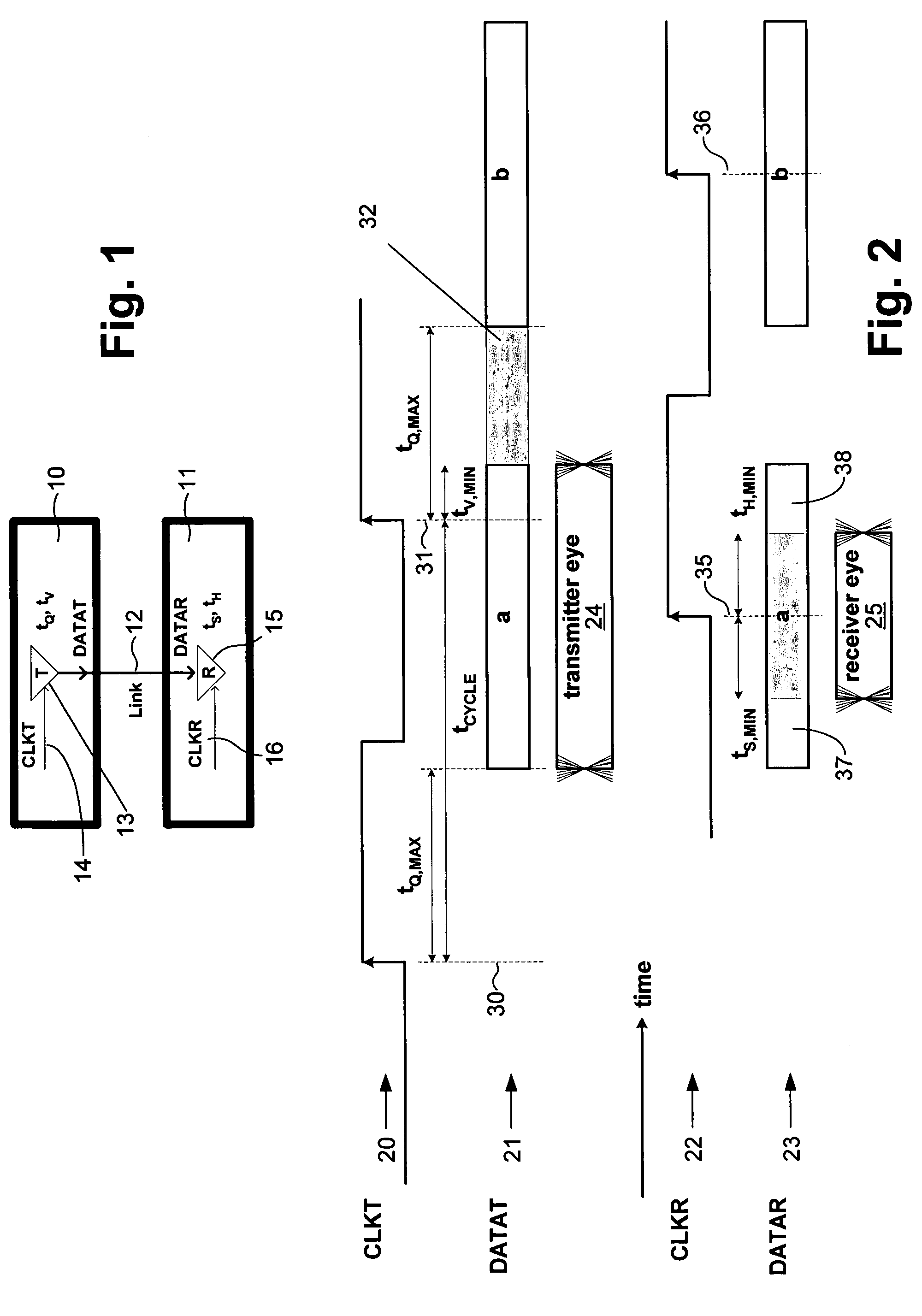
[0058]FIG. 1 shows two components 10, 11 connected with an interconnection medium, referred to as Link 12. One has a transmitter circuit 13 which drives symbols (bits) on Link 12 in response to rising-edge timing events on the internal CLKT signal 14. This series of bits forms signal DATAT. The other has a receiver circuit 15 which samples symbols (bits) on Link 12 in response to rising-edge timing events on the internal CLKR signal 16. This series of bits forms signal DATAR. FIG. 2 illustrates the timing parameters, including the transmit clock CLKT signal 14 on trace 20, the transmitter signal DATAT on trace 21, the receive clock CLKR signal 16 on trace 22, and the receiver signal DATAR on trace 23. The transmitter eye 24 and the receiver eye 25 are also illustrated. The transmitter eye 24 is a window during which the signal DATAT...


PUM


Abstract

A method and system provides for execution of calibration cycles from time to time during normal operation of the communication channel. A calibration cycle includes de-coupling the normal data source from the transmitter and supplying a calibration pattern in its place. The calibration pattern is received from the communication link using the receiver on the second component. A calibrated value of a parameter of the communication channel is determined in response to the received calibration pattern. The steps involved in calibration cycles can be reordered to account for utilization patterns of the communication channel. For bidirectional links, calibration cycles are executed which include the step of storing received calibration patterns on the second component, and retransmitting such calibration patterns back to the first component for use in adjusting parameters of the channel at first component.

Description

BACKGROUND OF THE INVENTION[0001]1. Field of the Invention[0002]The present invention relates to the calibration of communication channel parameters in systems, including mesochronous systems, in which two (or more) components communicate via an interconnection link; and to the calibration needed to account for drift of conditions related to such parameters during operation of the communication channels.[0003]2. Description of Related Art[0004]In high-speed communication channels which are operated in a mesochronous manner, typically a reference clock provides frequency and phase information to the two components at either end of the link. A transmitter on one component and a receiver on another component each connect to the link. The transmitter and receiver operate in different clock domains, which have an arbitrary (but fixed) phase relationship to the reference clock. The phase relationship between transmitter and receiver is chosen so that the propagation delay seen by a signal...

Claims


Application Information

Patent Timeline
Patent Type & Authority Patents(United States)
IPC IPC(8): H04B3/00H04B1/38H04L1/24H04L7/10H04L27/00
CPCG11C7/1057G11C7/1084G11C29/022G11C29/025G11C29/028H04L27/00H04L1/242H04L7/10H04L25/0292H04L25/12G11C7/04H04L7/0091H04L7/033G11C2207/2254H04L7/0016H04L7/0087
Inventor WARE, FREDERICK A.PEREGO, RICHARD EHAMPEL, CRAIG E
Owner K MIZRA LLC
Why Eureka
Try Eureka