PCM (phase change material) system and method for shifting peak electrical load

a phase change material and peak electrical load technology, applied in indirect heat exchangers, lighting and heating apparatuses, heating types, etc., can solve the problems of increased electricity rates, unsuitable pcm slurries, and too expensive to be used for shifting peak electrical load, so as to increase the specific heat of fluids, enhance the heat transfer off surfaces, and increase the heat transfer rate

Inactive Publication Date: 2006-08-29
LEADING TECH DESIGNS
View PDF22 Cites 10 Cited by
  • Summary
  • Abstract
  • Description
  • Claims
  • Application Information

AI Technical Summary

Benefits of technology

[0009]One of the advantages of using a paraffin slurry is the increase in specific heat of the fluid over a small temperature range. This increase leads to the ability to store large amounts of energy in a smaller volume of fluid.
[0010]Another advantage of using a paraffin slurry is to enhance the heat transfer off of surfaces. The particles interact with the boundary layer and have been found to increase the heat transfer rate by 30 percent or more. The combination of these characteristics leads to a small compact heat transfer system that can store significant amounts of energy. The advantage of using the fluid is in its ability to store large amounts of energy for small temperature changes. This characteristic gives the mixture the increased heat capacity.

Problems solved by technology

Peak A / C loads played a key role in driving up electrical demand, which caused power outages and raised electricity rates.
However, the research has found that these PCM slurries are not suitable and too expensive to be used for shifting peak electrical load.
The drawback of these materials is cost.
It is too expansive to be used for shifting peak electrical load type applications.
Higher PCM concentrations lead to smaller storage tank requirements.

Method used


Image

  • PCM (phase change material) system and method for shifting peak electrical load
  • PCM (phase change material) system and method for shifting peak electrical load
  • PCM (phase change material) system and method for shifting peak electrical load

Examples


Embodiment Construction

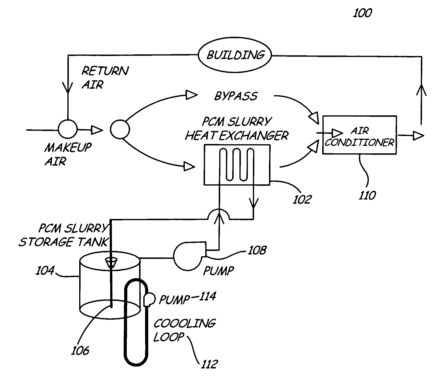
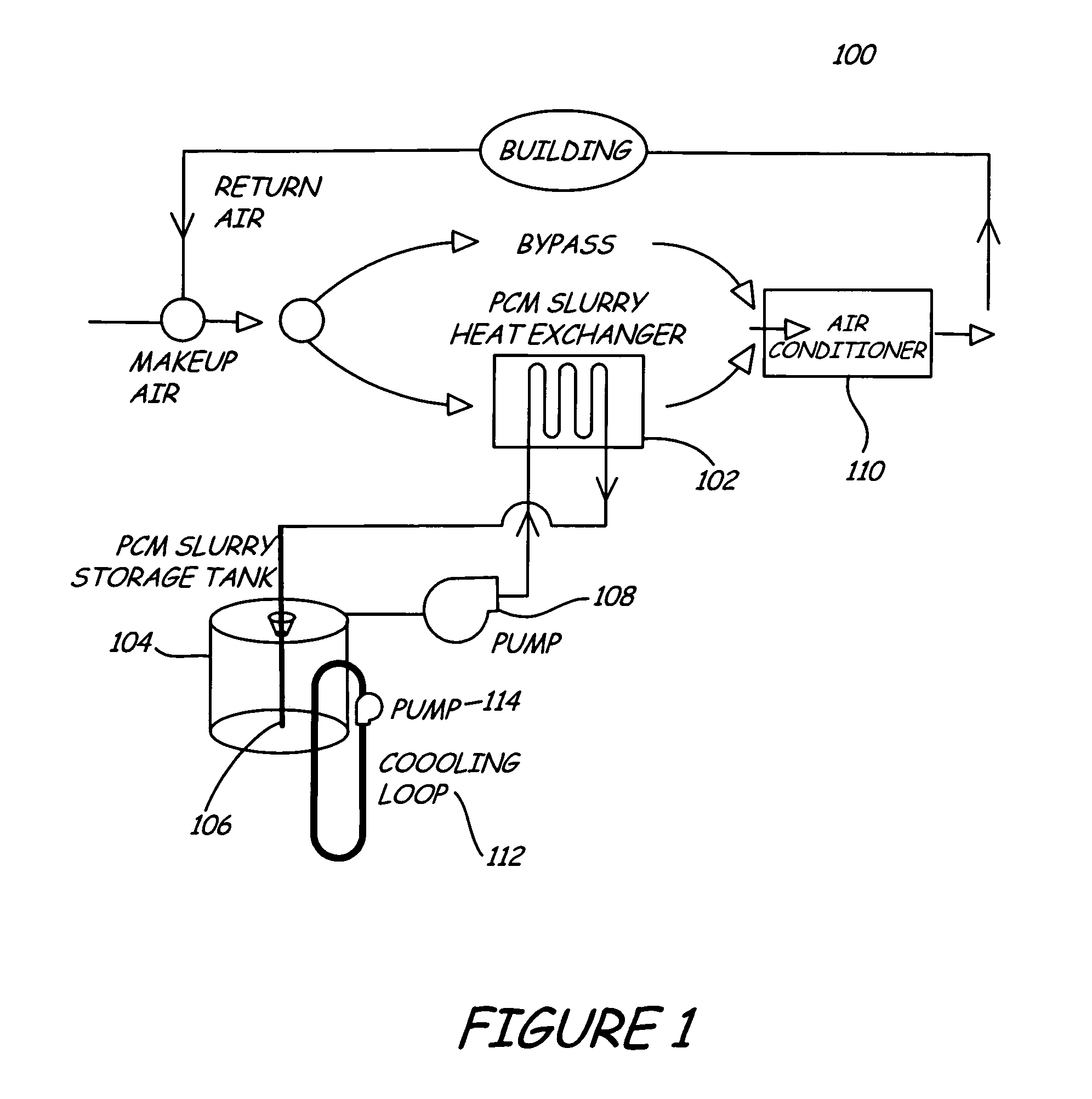
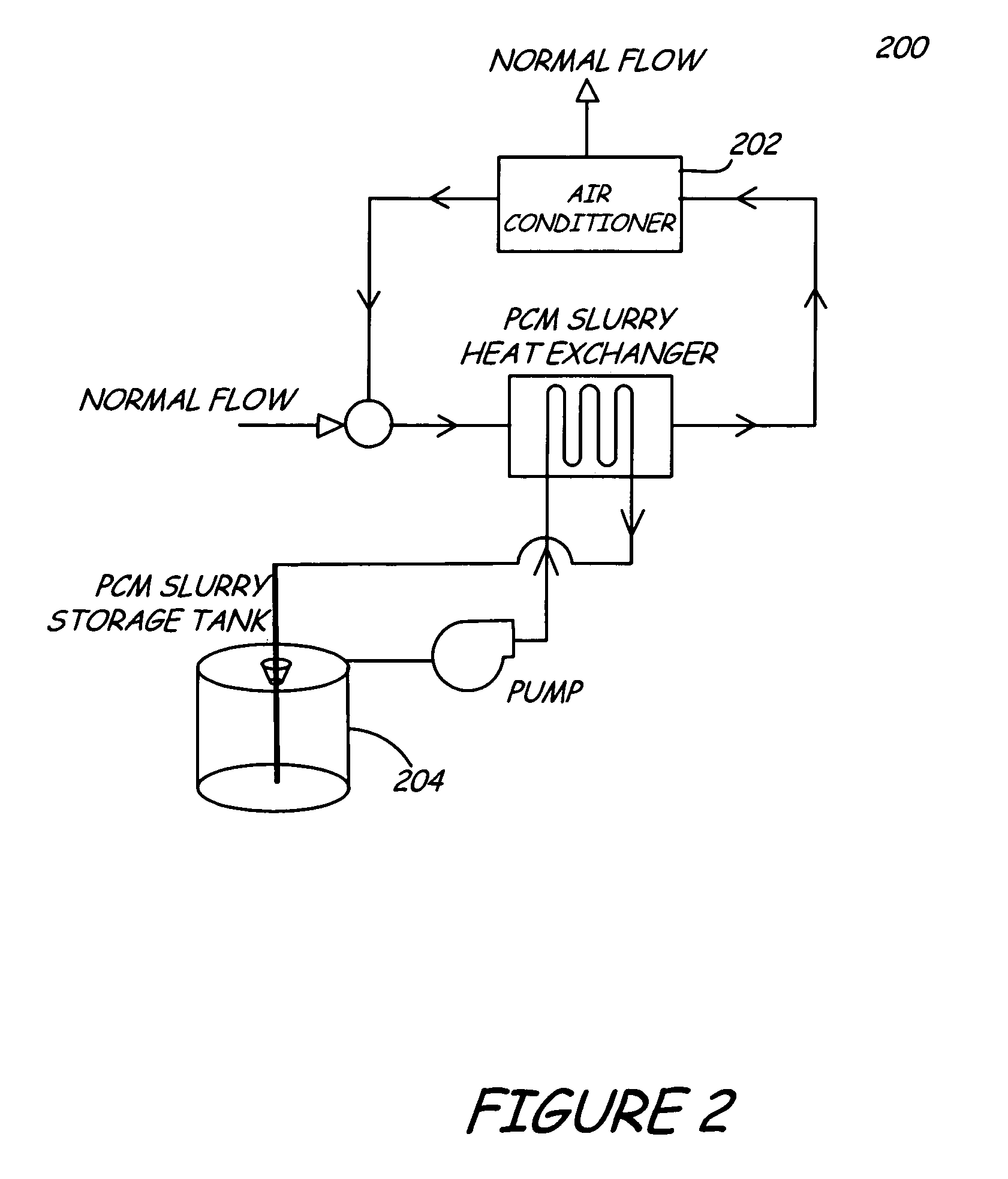
[0015]In the following description of a preferred embodiment, reference is made to the accompanying drawings, which form a part hereof, and in which is shown by way of illustration a specific embodiment in which the invention may be practiced. It is to be understood that other embodiments may be utilized and structural changes may be made without departing from the scope of the present invention.

[0016]For purposes of explanation, numerous specific details are set forth in the following description in order to provide a thorough understanding of the present invention. However, it will be evident to one of ordinary skill in the art that the present invention may be practiced without some of these specific details.

[0017]While this invention is susceptible of embodiment in many different forms, there is shown in the drawings and will herein be described in detailed preferred embodiment of the invention with the understanding that the present disclosure is to be considered as an exemplif...


PUM


Abstract

A PCM system and method of shifting peak electrical load is provided with a PCM system including a heat exchanger, a storage tank coupled to the heat exchanger for storing PCM slurry, a pump coupled to the heat exchanger, an air conditioning unit coupled to the heat exchanger, and a heat rejection unit coupled to the storage tank. The PCM slurry is pumped from the storage tank to the heat exchanger. The energy at the heat exchanger is absorbed by the PCM slurry, and the PCM slurry is then returned to the storage tank. The energy absorbed by the PCM is rejected from the storage tank to a ground loop or by an air conditioning unit during a non-peak or less load demand period.

Description

CROSS-REFERENCE TO RELATED APPLICATION[0001]This is a utility patent application which claims priority of U.S. provisional patent application Ser. No. 60 / 369,168, filed Mar. 29, 2002; subject matter of which is incorporated herewith by reference.FIELD OF THE INVENTION[0002]The present invention relates generally to peak electrical load shifting systems. More particularly, the present invention relates to a Phase Change Material (“PCM”) system capable of shifting peak electrical load.BACKGROUND OF THE INVENTION[0003]Peak electrical demand is heavily dependent on air conditioning (A / C) loads. Summer 2000 in California demonstrated the seriousness of the peak electrical demand problem. Peak A / C loads played a key role in driving up electrical demand, which caused power outages and raised electricity rates.[0004]Previous research has been conducted on the use of PCM slurries for electronics cooling and for district beating and cooling. However, the research has found that these PCM slur...

Claims


Application Information

Patent Timeline
Patent Type & Authority Patents(United States)
IPC IPC(8): F28D1/06F24F5/00F28D20/02
CPCF24F5/0017F24F5/0021F28D20/021Y02E60/147Y02E60/145Y02E60/14
Inventor CLARKSEAN, RANDY LEE
Owner LEADING TECH DESIGNS
Why Eureka
Try Eureka