Drill shoe

a drill shoe and drill bit technology, applied in the direction of drilling pipes, drilling/well accessories, sealing/packing, etc., can solve the problems of limiting the loading which can be placed on the drill shoe, reducing the life of the drill bit, and limiting the efficiency of drilling with the drillable drill shoe, etc., to achieve the effect of avoiding deformation

Active Publication Date: 2006-08-29
WEATHERFORD TECH HLDG LLC
View PDF648 Cites 72 Cited by
  • Summary
  • Abstract
  • Description
  • Claims
  • Application Information

AI Technical Summary

Benefits of technology

[0008]The present invention generally provides methods and apparatus for drilling of boreholes, wherein the drill string is used as the casing for the borehole, wherein the drill shoe used for drilling the borehole includes an integral displacement element whereby the cutting elements of the drill shoe are displaceable into the formation surrounding

Problems solved by technology

Thus the drill shoe needs to be configured of a drillable material, which limits the loading which can be placed on the drill shoe during drilling and thus limits the efficiency of drilling with the drillable drill shoe.
Additionally, although the main body of the drillable drill shoe is configured of a readily drilled material, the hard cutters of the drill shoe tend to cause rapid wear and physical damage to the drill shoe being used to drill through the previous drill shoe, thus reducing the life of the drill bit, and thus the depth of formation the drill shoe can penetrate before it t

Method used


Image

  • Drill shoe
  • Drill shoe
  • Drill shoe

Examples


Embodiment Construction

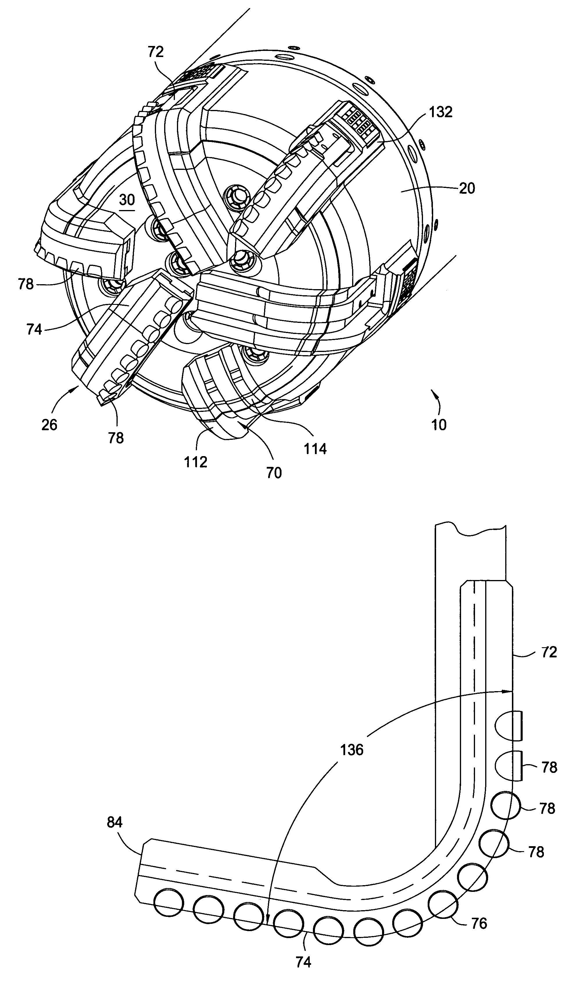
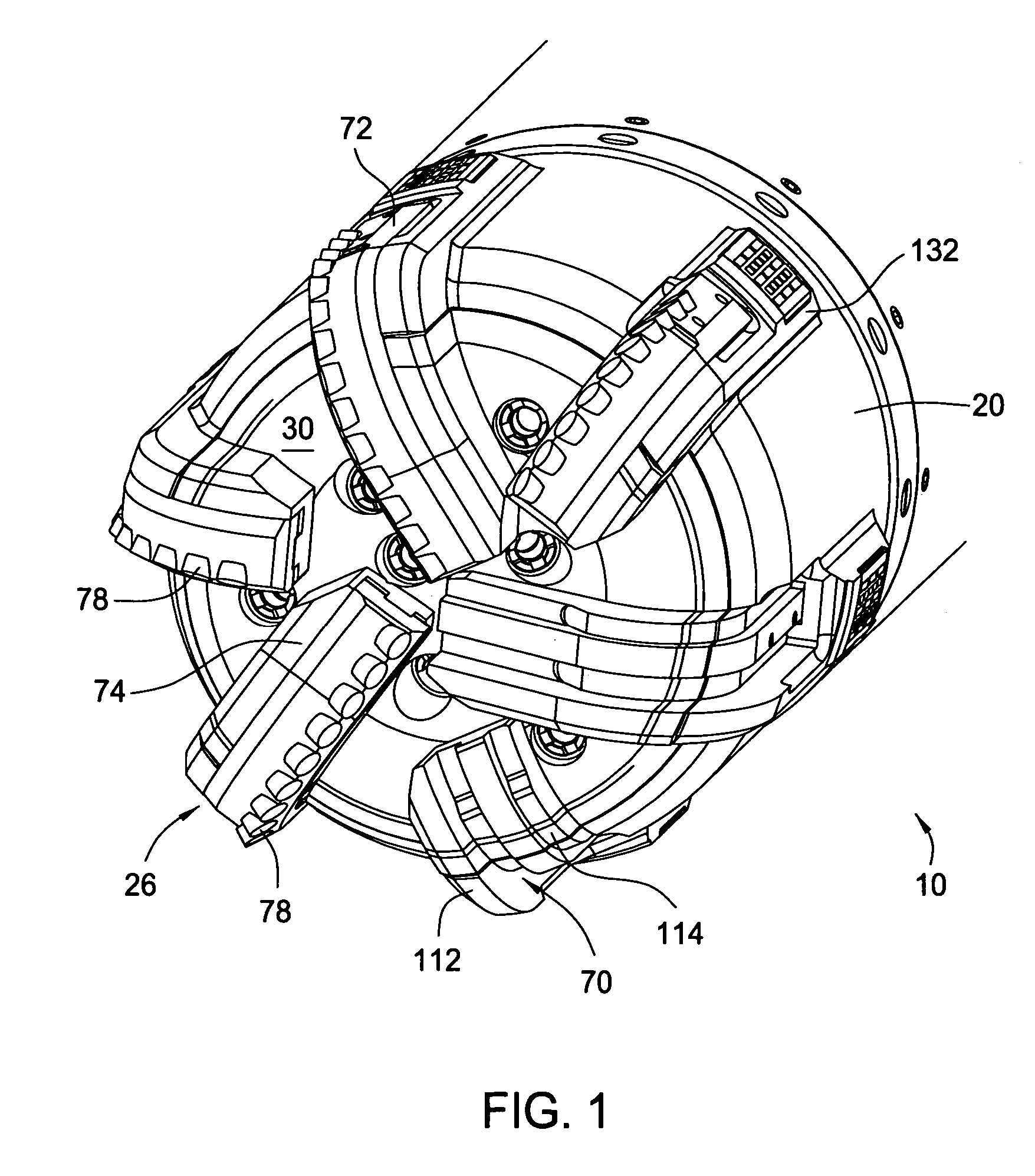
[0028]Referring initially to FIG. 1, there is shown in perspective an earth removal apparatus such as a drill shoe 10 of the present invention, for placement on the end of a string of casing for drilling a borehole into the earth, primarily for the recovery or potential recovery of hydrocarbons from sub-surface locations. The drill shoe 10 generally includes a support, such as a sleeve portion 20, into which is received a drillable member, such as a body portion 30, and over which are secured a plurality of cutting members or blades 26 (only four of a total of six to be so located) in notches 70 formed on the exterior of the drill shoe 10. The drill shoe 10 is specifically configured to enable the drilling of a borehole with the drill shoe 10, with subsequent cementing of the casing into the borehole, and then subsequent drilling through of the drill shoe 10 with a subsequent drill shoe 10.

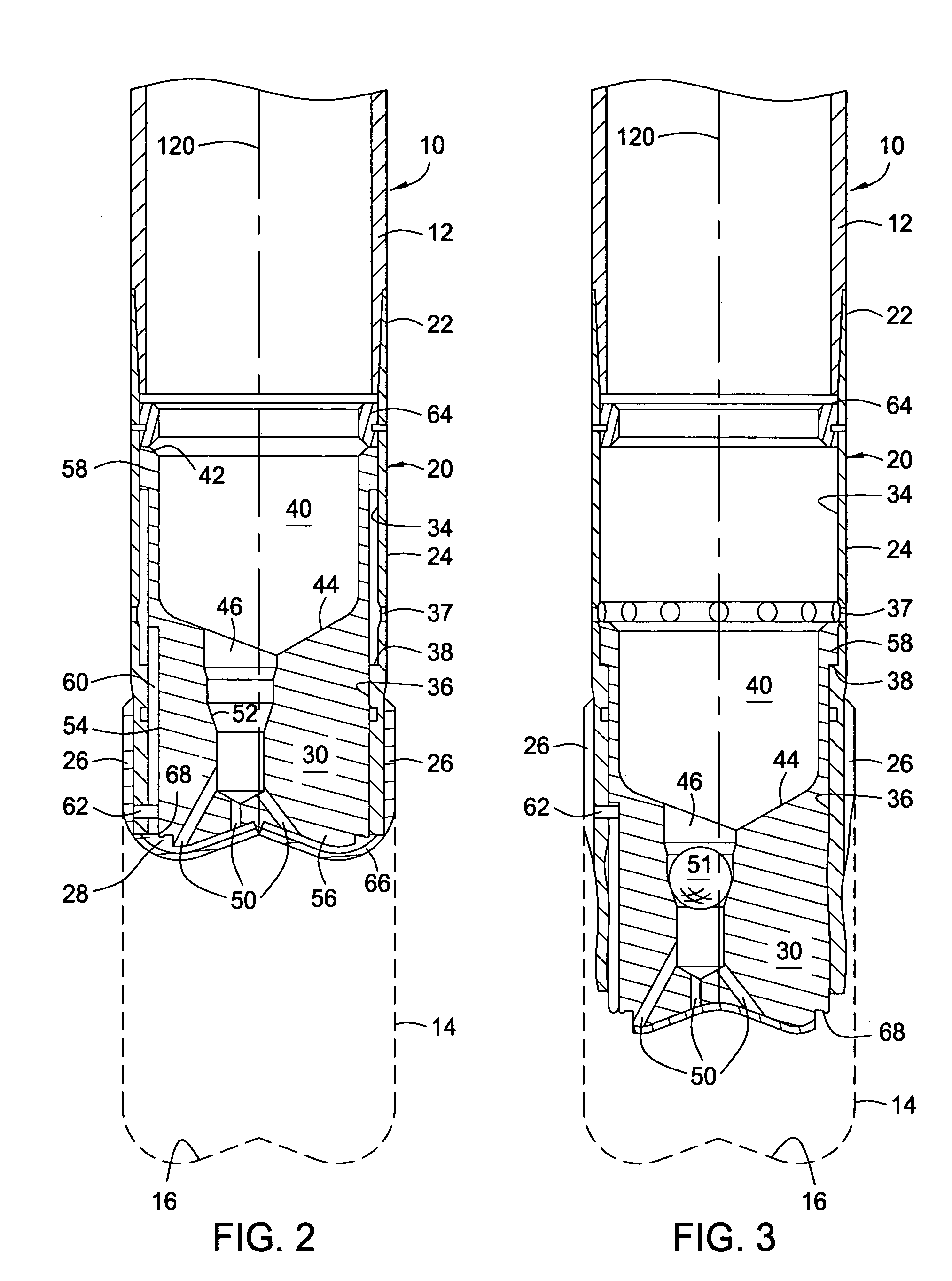
[0029]Referring now to FIGS. 2 and 3, there is shown, in cross section, the drill shoe 10 of t...


PUM


Abstract

A method and apparatus for a drilling with casing includes therewith a drill shoe configured for later drilling through thereof in situ, with cutters retainable thereon in response to the forces encountered during borehole drilling, yet moveable from the envelope through which the later drill shoe will pass when cutting through the in situ drill shoe. The drill shoe includes one or more profiles thereon, into which blades carrying the formation drilling cutters are disposed. The profiles include at least one projection thereon, which is received within a mating slot in the blades. The blades also may be configured to have opposed sections which are configured with respect to one another to have an included angle of less than ninety degrees.

Description

CROSS REFERENCE TO RELATED APPLICATION[0001]This application claims benefit of co-pending U.S. Provisional Patent Application Ser. No. 60 / 450,432, filed on Feb. 27, 2003, which application is herein incorporated by reference in its entirety.BACKGROUND OF THE INVENTION[0002]1. Field of the Invention[0003]Embodiments of the present invention generally relate to the field of well drilling, particularly to the field of well drilling for the extraction of hydrocarbons from sub-surface formations, wherein the drill string is used as the well casing.[0004]2. Description of the Related Art[0005]The drilling of wells to recover hydrocarbons from subsurface formations is typically accomplished by directing a rotatable drilling element, such as a drill bit, into the earth on the end of tubing known as a “drill string” through which drilling mud is directed to cool and clean the drilling face of the drill bit and remove drilled material or cuttings from the borehole as it is drilled. After the ...

Claims


Application Information

Patent Timeline
IPC IPC(8): E21B10/20E21B7/20E21B10/62E21B10/627E21B17/14E21B21/10
CPCE21B7/20E21B10/62E21B21/103E21B17/14E21B10/627E21B34/10
Inventor MCKAY, DAVIDHAUGEN, DAVID M.
Owner WEATHERFORD TECH HLDG LLC
Why Eureka
Try Eureka