Printheads having improved heater chip construction

a technology of heater resistors and print heads, which is applied in printing and other directions, can solve the problems of poor adhesion of nozzle plates, prone to misdirection of print heads, and poor operation, and achieve the effects of enhancing the planarity of the chip, and reducing the energy difference between heater resistors

Active Publication Date: 2006-08-29
FUNAI ELECTRIC CO LTD
View PDF33 Cites 4 Cited by
  • Summary
  • Abstract
  • Description
  • Claims
  • Application Information

AI Technical Summary

Benefits of technology

[0012]The inactive heater array provides a region adjacent the end of the active heater array that is substantially planar, and also provides a plurality of current paths which reduce energy differences in heaters resistors adjacent the end of the active heater array when compared to other heater resistors in the heater array.
[0013]The present invention provides an improved heater chip construction that achieves a number of specific advantages over conventional heater chips and print heads. For example, the invention enhances the planarity of the chip and reduces the energy difference between heater resistors adjacent the end of a heater array, resulting in improved print head performance and life. Enhanced planarity is achieved by including an additional, but inactive, heater structure adjacent the end of the active heater array. The inactive heater structure serves to relocate the abrupt topographical variations sufficiently remote from the end of the active heater array. Reduced topographical variations facilitate attachment of a nozzle plate to the chip in a manner that improves nozzle plate adhesion and also reduce distortion of ink ejection paths through nozzle holes in the nozzle plate. The improved planarity also results in an increased thickness of the planarizing layer on the chip adjacent the end of an active heater array, thereby improving corrosion resistance of the active heater array structure.
[0014]The inactive heater structures also increase the available current paths, thereby decreasing the energy difference of heater resistors adjacent the end of the heater array compared to other heater resistors in the heater array. A reduction of the energy difference achieved by the chip construction helps provide more consistent heater resistor energy characteristics, resulting in improved ink bubble performance and print performance.

Problems solved by technology

However, improvements in print speed and quality often result in operational problems not experienced with lower quality slower speed printers.
Defects in conventional chips result in print heads that are prone to misdirected ink drop ejection, poor nozzle plate adhesion, and reduced corrosion resistance.
Although a 0.6° deviation from ideal may appear to be minor, the resulting droplet misplacement is significant given the distance the droplet travels before impacting the recording medium and the high placement precision required for quality printing.

Method used


Image

  • Printheads having improved heater chip construction
  • Printheads having improved heater chip construction
  • Printheads having improved heater chip construction

Examples


Embodiment Construction

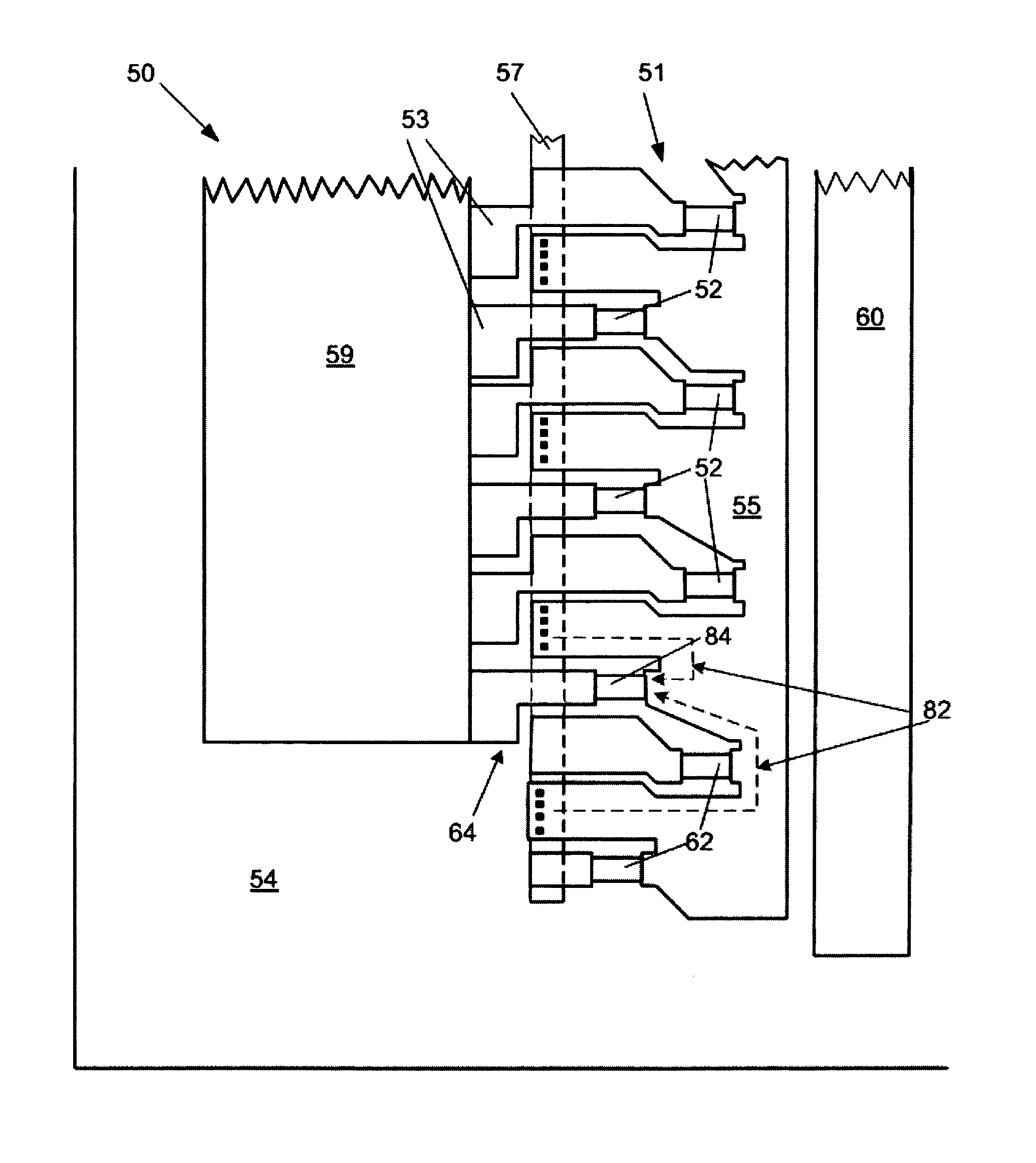
[0024]The present invention provides an improved heater chip having one or more inactive heater structures, such as inactive heater resistors, located adjacent the end of the active heater array. Use of inactive heater resistors advantageously shifts abrupt topographical variations away from the end of the active heater array so that the topographical variations have considerably less impact on a nozzle bore angle and ink droplet trajectory. The inactive heater resistors also increase the available current paths, thereby decreasing the energy difference between heater resistors adjacent the end of the heater array and other heater resistors in the heater array.

[0025]In a preferred embodiment, and with reference to FIG. 4, the invention provides a heater chip 50 having a heater array 51 containing a plurality of active heater resistors 52 formed on a device side 54 thereof. A nozzle plate 56 (FIG. 6) having ink ejection nozzle holes 58 corresponding to the active heater resistor site...


PUM


Abstract

An improved heater chip for an ink jet print head, the chip including an active heater array and an inactive heater array located adjacent to and extending away from the end of the active heater array. The inactive heater array provides a region adjacent the end of the active heater array that is substantially planar, and also provides a plurality of current paths which reduces energy differences between heater resistors adjacent the end of the active heater array and other heater resistors in the heater array.

Description

FIELD OF THE INVENTION[0001]The invention relates to heater chips for ink jet printers and specifically to print heads having improved heater chip construction.BACKGROUND[0002]Ink jet technology continues to be improved in order to increase printing speed and print quality or resolution. One means for improving print speed and quality is to increase the number of nozzle holes in an ink jet print head and to decrease the diameter of the nozzle holes. However, improvements in print speed and quality often result in operational problems not experienced with lower quality slower speed printers.[0003]In an ink jet printer, ink is provided to the print head from an ink cartridge or supply tank. The ink flows from the tank through a connecting conduit from the ink cartridge through an ink via in a semiconductor chip or around the edges of a semiconductor chip and into ink flow channels and an ink chamber. Each ink chamber is situated in axial alignment with a corresponding nozzle hole and ...

Claims


Application Information

Patent Timeline
Patent Type & Authority Patents(United States)
IPC IPC(8): B41J2/05B41J2/135B41J2/14
CPCB41J2/14129B41J2/14072
Inventor HUBERT, RICK L.PARISH, GEORGE K.ROWE, KRISTI MEDELEN, JOHN G.GRAF, PAUL W.SULLIVAN, CARL
Owner FUNAI ELECTRIC CO LTD
Why Eureka
Try Eureka